")


")
Produced Water-and Separation and Treatment System for Oil Contamination Reduction
1 Introduction
Water produced in extraction of oil and gas is perhaps the most significant waste stream produced by the oil and gas sector, by volume. The oil and gas industry produces about fourteen billion bbls of water per year (Veil, Puder, Elcock and Redweik, 2004). The quality and quantity of water produced varies greatly and in some cases, it is can be used as a by-product or even sold as a commodity in the market. However, produced water is often considered to be a waste, but this is changing in the industry as firms are beginning to consider it as a potential resource from which value can be gained.
Regardless of whether produced water ends up as a waste or a commodity, there are management costs that should be minimised with each production site and region of operation. Otherwise it has the potential to adversely affect the life of the well and may result in substantial recoverable reserves being left in the ground (Arthur, Langhus & Patel, 2005). In addition, the practices that are used by a firm to handle produced water should be environmentally safe, or else the operator could be faced with regulatory action. The methodology adopted in the management of produced water depends largely on the composition of the produced water, the location, availability of resources, and the quantity.
Arthur et al (2005) states that some of the options available to an oil and gas company for the management of produced water include; avoiding production of water onto the surface, injecting produced water, discharging produced water, reusing in the oil and gas production operations, and consumption in any other beneficial way.
One of the ways that has been proven to an effective method of handling produced water is treatment (Veil et al. 2004; Arthur et al. 2005). According to studies done to identify, verify, and compile existing newly developed techniques, it has been demonstrated that there are economical benefits to the treatment of produced water. The treatment of produced water has the advantage that it can help in the adoption of other water management options for example, beneficial uses that have the potential to deliver social and economic advantages.
Treatment of produced water is a requirement in most instances before the water can be put to other uses. Treatment of water is done primarily to remove oil and other contaminants that might cause environmental or health problems.
The selection of a water treatment solution is a challenging problem, The selection should be chosen on the basis of economics, but must guarantee the required output criteria (Igunnu and Chen 2012; Arthur et al. 2005).
1.1 Background
Natural water (also known as formation water) is always found together with petroleum in reservoirs. This water is slightly acidic and it is found below the hydrocarbons in a reservoir media that is porous (Igunnu and Chen, 2012). In the extraction of oil and gas, continued extraction leads to pressure reduction in the reservoir and thus water has to be injected into the reservoir water layer for the purpose of maintaining the hydraulic pressure and facilitate recovery of oil. There can also be water from outside the reservoir area and as the extraction continues, formation water will reach the production well. As a result, alongside production of hydrocarbons, water is also produced, and this is often referred to as oilfield brine (Igunnu and Chen, 2012).
The rate of oilfield produced water production in any given well increases as the oilfield ages (Sutherland, 2012; Devold, 2009). On the average production rate, oilfields produce more than 60% of daily produced water at a global scale. In addition to age, other factors have been found to affect the quantity of produced water that is produced in an oilfield throughout its life.
Generally, the composition of produced water includes dissolved and dispersed oil components, dissolved formation minerals, dissolved gases, produced solids, and dispersed oil components, as a result of the geographical formation, the type of hydrocarbon, and reservoir age, the variation of organic and inorganic components is very wide.
The chemical components of the water largely determine the oil recovery method, which is basically a separation operation to extract the oil and gas from the extract. The major separation process in the process is that of oil and water, followed by the purification of gas (Igunnu and Chen, 2012). Given these two scenarios, it then means that the bulk of the work is in settlement using knock-out drums, and API (American Petroleum Institute) and lamellar separators. This method is the standard approach in the oil extraction industry, but new techniques are emerging, especially centrifugal oil/water separators which are mainly used in offshore rigs because energy costs are relatively low (Sutherland, 2012).
Based on the need for greater separation efficiency and improved quality requirements of produced water, new systems are being developed. The most apparent development is the adoption of membrane systems in removing the last traces of oil in the effluent. In addition to the removal of oil traces, membrane separation is also being used in the preparation and recycling of injection fluids and other fracking fluids.
The value of produced water is almost zero if the hydrocarbons are not removed and it is even a problem to dispose of since many of the oil producing regions have laws that illegalize disposal of untreated produced water into the environment (Igunnu and Chen, 2012).
As discussed earlier, produced water is made up of the layer of water found under the oil layer in the reservoir as well as the injected water used to boost the well pressure to enhance extraction. As a result, the quantity of produced water increases through time, and investing in a produced water treatment system is a requirement. Normally, the complex mixture extracted from the well should be treated and disposed of in the vicinity of the well, particularly in the case of offshore wells, but the complexity of the water associated with contaminants creates a serious and expensive operational problem for the well operator.
As produced water leaves the well site, the quality requirements depend on where the site is located; onshore or offshore, close to a town or far from human habitation, shallow or deep sea. Produced water in its untreated state is more saline than sea water. Therefore, it is impossible to dispose it of back to the sea as such an action would cause a significant disturbance of the marine environment. In addition, it cannot be discharged onto the land unless its salt content is reduced or completed removed (Ahmadun et al. 2009). This affirms that produced water can be used, but only after it is suitably treated.
One of these uses is re-injection into the formation to promote oil flow. For produced water to be re-injected into the formation, it is required that is should be able to flow through the small passageways in the rock. This means produced water has to be filtered free of fine solids before it can be re-injected. In the case of reuse of produced water by reinjection, it might not be necessary to remove all oil traces thoroughly before reinjection.
The treatment of produced water is therefore mainly determined by the disposal method. Towards this end, oil producing companies will opt for the method that is cheapest, or has economic benefits. as a result, recycling of produced water, mainly through reinjection into the well formation is the most preferred method for disposing produced water as the only primary treatment method is filtration which can be done using deep bed (sand) filters.
1.2 Aim and Objectives
The study seeks to explore the handling of produced water in a case study setting. A case study setting is sure to lighten up the operations involved in handling of produced water as well as the latest technology being used. Thus, the purpose of the study is to explore the opportunity for latest technology deployment in Libyan Oil field.
1.2.1 Study objectives
- To conduct a literature review of the management and treatment of produced water.
- To consider the current water quality of produced water in Libya and other regions.
- To identify which technologies are suitable for the enhancement of produced water quality.
1.3 Dissertation structure
This dissertation is divided into seven chapters:
Chapter one provides and introduction and provides a background to the subject area, i.e. produced water in the oil and gas industry and its treatment. In particular, the background covers the recovery of oil from onshore/offshore well formations that involve oil/gas water mix and the treatment of produced water to enhance its disposal in whichever way preferred by the well operator. The chapter also covers the purpose of the study and the study objectives.
Chapter 2 is a review of the relevant literature. First, the process involved in oil production is described as these largely determine the components of produced water. Then how produced water becomes a by-product in the oil and gas extraction process is highlighted. This is followed by a discussion on the technologies that are available for the treatment of produced water. The technologies are covered with emphasis in the popularity of the technology in the industry as well as emerging technologies. The quality of produced water varies across geographical locations and therefore some consideration is given to the required standards of produced water discharges across the United Kingdom (UK), United States of America (USA), the Middle East, and Libya. Finally a description is given of the state of Libyan oil and gas industry with a focus on the Mellitah Oil and Gas Company (MOG).
Chapter 3 covers the methodological approach used in the study. A case study methodology is used with two study cases; Mellitah Oil and Gas Company and Shell. For the case of MOG Company, study is done to establish and examine the current separator technology for the treatment of produced water with particular interests in establishing the quality of the water. For the case of shell, the study is done to establish and examine both the offshore and onshore solution for the treatment of produced water.
Chapter 4 presents the study results. The study findings are presented in three sections, referred to as solutions. Solution one is the use of latest technology for the treatment of produced water to generate water with less oil contamination that is to be disposed to the environment. The second solution is the use of produced water after it has been treated for the purpose of reinjection into the reservoir. Solution three presents any other uses that might exist in the Oil and gas plants under study. Lastly in the chapter is a discussion on the study findings.
Chapter 5 is the study conclusion. The chapter basically draws determinations as guided by the study objectives. Thus, the conclusion presents a summary of the literature on produced water treatment, the current standards of produced water quality in the primary oil and gas producing areas in the world, and the technologies that are best suited for the enhancement of the quality of produced water.
Chapter 6 covers the materials that have been used in the study under references and chapter 7 presents the materials that have been essential in the completion of the study under appendixes.
2 Literature Review
2.1 Oil Production Process
The oil and gas production process is broadly defined in terms of its use in the oil and gas production stream. These include exploration, upstream, midstream, refining, and petrochemical (Devold, 2013). Upstream is typically the phase of production and stabilization of oil and gas and midstream is the oil and gas treatment phase.
While in the past exploration involved inspection of surface features, among them tar seeps or gas pockmarks, today exploration is carried out using a series of surveys that start with a broad geographical mapping. Geographical mapping is done through increasingly advanced methods for example; passive seismic, magnetic and gravity surveys that give data to advanced analytic tools that identify the potential for rocks rich with hydrocarbon.
Oil production is either offshore or onshore and each requires specific and specialized technologies to process the oil and gas being extracted. In addition, the natural state of the resource, unconventional or conventional is also a factor to consider in the production process of oil and gas.
The general oil production process commences in the upstream phase at the wellhead. Once drilling is completed and a well verified to be commercially viable of natural gas or oil extraction, it has to be “completed” to allow for the resource to flow out. This process involves strengthening the oil well hole with casing, evaluation of the temperature and pressure of the formation, and installation of the proper equipment to allow for efficient flow of the resource (Argonne National Laboratory et al. 2004). The process of completion is differentiated into dry completion and subsea completion which are onshore and below the surface respectively. In offshore oilfields, dry completion wells located on the main field feed into production manifolds directly while the outlying wellhead towers and subsea installations feed to the production risers through the multiphase pipelines. Production risers are a system that a pipeline to rise to the topside structure (Devold, 2013).
For onshore oil production to be economically viable, it has to be from several tens of barrels a day or more. The oil gathering network can be very large with production from thousands of wells which are a hundred kilometres apart and feed to a plant through a gathering network. However, the oil extraction process will depend on the nature of the well, with the easier method being for free-flowing wells. For the small reservoir, extracted oil is collected in a holding tank from where it is picked on regular intervals by railcars or trucks for processing at a refinery (Devold, 2013). For onshore wells that are located in oil-rich areas, production can be up to thousands of barrels per day and this is sent from the plant to a refinery through a pipeline or tankers. Ordinarily, oil into a refinery can be from various license owners and this makes metering of individual well-streams necessary.
2.1.1 Unconventional Oil
Unconventional oil production targets crude oil that is very heavy or tar sands which can become economically extractable with new technology with such oil attracting higher prices. To be extracted, heavy crude oil may need to be first heated and/or diluted. Tar sand are strip-mined or extracted with steam having lost their volatile compounds (Devold, 2013). With drilling technology and reservoir fracturing techniques which began in 2007, it is possible to produce shale gas and liquids in higher volumes. As a result, the US, in particular, has been able to reduce her dependence on hydrocarbon import. Other countries that are increasingly producing unconventional crude oil are Canada, China, Russia, Australia, Mexico, and Argentina. The hydrocarbons found in unconventional reserves may be more two to three times than those found in conventional reservoirs.
2.1.2 Offshore production
In offshore oil production, a range of different systems are used and these depend on the scale of production and water depth. In the recent years, there has been an increase in the pure sea bottom installations that are connected to multiphase piping to the shore and with entirely no offshore topside structures (Devold, 2013). These new developments have replaced the outlying wellhead towers and deviation drilling is being used to reach the different parts of the reservoir from few locations of the wellhead clusters. Some of the common structures used in offshore oil production process are:
- Shallow water complexes – several independent platforms that have different parts of the process and utilities are linked with gangway bridges. Each of the platforms has wellhead riser, accommodation, processing, and power generation platforms.
- Gravity base – huge concrete fixed structures that are placed on the bottom, normally with oil storage cells in a “skirt” that is on the bottom of the sea. All parts of the process and utilities are received by the large deck in large modules.
- Floating – compliant towers, floating production which includes Production Storage and Offloading (FPSO), Tension Leg Platform (TLP), semi-submersible platforms, and Single Point Anchor Reservoir (SPAR), and subsea production systems.
Shallow water complexes, which are Gravity base is made up of compliant towers which are more like fixed platforms are made up of a narrow tower that is attached to a foundation on the seafloor and extends up to the platform (Devold, 2013). The tower is flexible therefore it can operate in a much deeper water level for it can absorb much of the pressure exerted by the sea and the wind. Subsea production systems involve wells that are located on the floor of the sea with petroleum extracted at the seabed and “tied-back” to an offshore facility of a pre-existing production platform. The well is drilled using a movable rig and the oil extracted is transported through an undersea pipeline and to a processing facility using a riser.
Floating production, on the other hand, has all the topside production systems located on a floating structure with subsea or dry wells. The first is the FPSO which is a standalone structure which doesn’t need external structures like storage or pipelines. Crude oil is offloaded to a shuttle tanker on a regular basis and depending on the storage capability. The second is the TLP which is made up of vertical tendons that are connected to the sea floor by pile-secured templates and they hold the structure in place. The third floater type is semi-submersible platforms which have a similar design to TLP but without a taut mooring which allows for more vertical and lateral motion. Semi-submersible platforms are used generally with flexible risers and subsea wells. The last floating production type is the SPAR which is made up of a single tall floating cylindrical hull which supports a fixed deck (SPAR is not an acronym and it gets its name from its resemblance to a ship’s spar). The cylinder is tethered to the bottom by a series of cables and lines and it does not extend all the way to the seabed (Devold, 2013).
2.1.3 Onshore Production
In onshore production, the individual well streams are brought into the main production centre through a network of pipelines and manifold systems. The purpose of these gathering pipelines is to allow for the creation of “well sets” to allow for the selection of the well with the best reservoir utilization flow composition (Devold, 2013). In offshore, the dry composition wells that are located in the main field feed directly into the production manifolds while the subsea installations and outlying wellhead towers feed through multiphase pipelines that flow back into the production risers. Risers are a system of pipes that rise to the top of the production structure (Devold, 2013). The next phase in the production process is separation.
The resource from a given well will vary greatly. While some wells have for instance pure gas that can be taken directly for treatment, others will have a combination of gas, oil, and water with other various contaminates that must be processed and separated. Separation facilities are in various forms and design with the classic variant being the gravity separator (Devold, 2013). In this process, the oil well resource flow is directed into a horizontal vessel with a retention period of about five minutes to allow for gas to bubble out, the water fraction to settle at the bottom and for oil to be taken out t the middle level. The pressure level is often reduced in several stages so as to allow for controlled separation of the components depending on their volatility.
2.1.4 Mid-stream production
With oil removed from the mixture, it is subjected to another treatment process to remove any contaminants that could include mineral components as well as further processing to achieve the various final commercial products. From this process, water is simply a byproduct of the process and in the modern day oil and gas industry, this has become a useful resource for various uses among them, reinjection into the well. However, before it is used for whatever option the firm deems suitable, it has to be treated to the required standard as per the given use.
Before oil is loaded on a vessel, which marks the final stage of the upstream phase, it is stored. In offshore production facilities, those without a direct pipeline connection will normally rely on crude storage in the hull or base, and then a shuttle tanker offloads it periodically. For the larger production complexes, they generally have an associated tank farm terminal which allows for storage of the different grades of crude oil hence accommodating for demand changes, transport delays, and other unexpected inconveniences in the supply chain. The role of metering stations is to allow operators to manage and monitor the natural oil exported from a production facility. To effectively and successfully implement this duty, these stations use specialized meters to measure oil as it flows through the pipeline and thus not impeding its movement. Such metering measures the volume transferred to a consumer or other divisions within the company and it is referred to as transfer metering (Devold, 2013). The importance of this type of metering is that it forms the basis for invoicing the transferred product and allow for calculation of taxes and revenue sharing among the partners.
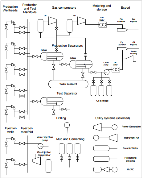
Figure 2.1: Oil production overview (adopted from Devold, 2013)
2.1.5 Downstream Production
In the tail end processes in the production of oil is refining, which is done for the purpose of providing a defined range of products based on agreed specification. The simple refineries have a distillation column for the separation of crude into fractions with the relative quantities of each fraction being directly dependent on the crude used (Devold, 2013). To produce the required quantity and quality of end products, it is necessary to obtain a variety of crudes which can be blended to a suitable feedstock. Moreover, this strategy has become really essential for it is one of the methods that can guarantee the economic viability of a modern refinery through the use of various methods among them cracking, reforming, additives, and blending. Crude blending has the potential to produce products that can meet the demands of the market both in quality and quantity at premium prices. The role of a refinery is not limited to refining but also includes operating products distribution terminals which dispense their products to bulk customers, for example, gasoline stations, airports, industries, and ports.
2.2 Produced Water as a by-product
Naturally occurring rocks in a subsurface formation are generally permeated with fluids among them oil, gas, and water or some combinations of these fluids. As argued by Saththasivam, Loganathan and Sarp (2016), the rock with the most oil-bearing formations is entirely saturated with water before the oil and gas extraction process begins. The formation of hydrocarbon reservoirs is through the less dense hydrocarbons migrating to the trap locations and displacing some of the water from the formation. As a result, reservoir rocks will normally contain both water and petroleum hydrocarbons, i.e. liquid and gas. The source of the water could include both above and below the hydrocarbon zone, from within the hydrocarbon zone, or flow from fluids injected and additives during the extraction and production process. As this stage, this water is referred to as “formation water” or “connate water” and its names changes to produced water after the reservoir is produced and the fluids extracted to the surface.
Produced water, therefore, is any water present in a reservoir occurring with the hydrocarbon resource and it is produced to the surface as a mixture with the natural gas or the crude oil. On production, hydrocarbons are a mixture of fluids and solids and it’s typically composed of gaseous or liquid hydrocarbons, dissolved or suspended solids, produced water, produced solids which include sand and/or silt, and injected additives and fluids that are placed into the formation with the aim of enhancing the exploration and production processes (Argonne National Laboratory et al. 2004).
In the process of oil and gas extraction, produced water is produced as a byproduct. It is certainly not the product of interest in the drilling process. Owing to the fact that water is a naturally occurring substance in any geographical environment, it is impossible to avoid water in the extract during oil and gas extraction and production regardless of how sophisticated the equipment is. As a result, it becomes essential that the water component in the oil and gas extract is separated at the initial stages of oil and gas process resulting to produced water.
Despite being a byproduct in the oil and gas production process, produced water has become a major factor in the oil and gas industry with respect to environmental pollution and the volume of produced water globally. Produced water is made up of various elements and thus, it is not a single commodity. The properties of produced water, both chemical and physical vary greatly depending on the geographical location of the oil field, the geological formation which the produced water has been in contact with hitherto, and the type of hydrocarbon being produced (Kharoua et al. 20l3). Research has shown that the properties of produced water, as well as the volume produced in a given well, can vary throughout the lifetime of the well. Additionally, if waterflooding operations are implemented, then the properties and volumes of produced water could vary even more dramatically as injected water is introduced into the reservoir’s formation.
Given the increased interest in produced water, knowledge of the components of the specifically produced water is important for compliance with regulations in choosing the appropriate management option. Various produced water disposal strategies are available and the most appropriate are chosen by a given oil and gas company based on mainly economic benefits. Some of the most common produced water disposal strategies include reinjection into the well. In both offshore and onshore oil and gas production, oil and grease receive the most attention as constituents of produced water with salt content, expressed in terms of salinity, Total Dissolved Solids (TDS), or conductivity, being the primary constituent of concern in onshore oil and gas production operations. In addition to these, other elements in produced water are both organic and inorganic compounds and these vary greatly depending on geographical location and time of the well (Saththasivam et al. 2016).
Given the nature of produced water, it is generally impossible to remove the various components through the basic and popular gravitational separation technology thus additional treatment technologies are required. There are various produced water treatment methods and the choice of any is dependent on a number of factors among them; the nature and constituents of the produced water, oil and gas firm capabilities, the disposal method available for the produced water, and economic benefits.
2.3 Treatment Technologies
The approaches available for the treatment of produced water are many. The appropriate option will largely depend on the geographical location of the oilfield, the regulatory framework applicable, technical feasibility by the given oil and gas firms, cost, and the presence of the right equipment and infrastructure. The most common options that are being used currently for the management of produced water include; underground reinjection, beneficial reuse, and discharge into the environment (Saththasivam et al. 2016; Argonne National Laboratory et al. 2004). In the past, the methods used were basically chosen based on convenience and those that are least expensive. Given this shift, and the realization by oil and gas production firms that produced water can either be of value or a cost to the overall operations, new produced water treatment methods are available and largely used in the industry today. The technological options available include gravity settling (skim vessels, API separator, and parallel and corrugated plate separation), hydrocyclone, chemical treatment, coalescing media, gas flotation, media filtration, and membrane separation.
2.3.1 Membrane filtration technology
This technology uses membranes which are microporous films with pore ratings, and they selectively separate a fluid by filtering out the various components. There are four established membrane separation methods; ultrafiltration, microfiltration, reverse osmosis, and nanofiltration (Xu & Drewes, 2006). The four technologies all work through different mechanisms to separate the fluid with the constituents. Reverse osmosis separates ionic and dissolved components, microfiltration separates particles suspended in the produced water, ultrafiltration separates macromolecules, and nanofiltration is a selective method separating multivalent ions. While microfiltration and ultrafiltration technologies can be used as standalone strategies for the treatment of produced water, reverse osmosis, and nanofiltration technologies have to be employed in the desalination of produced water (Padaki et al. 2015). Nanofiltration and reverse osmosis are therefore the best-suited treatment technologies when seeking to reduce the salt content of produced water, which is common for offshore production where produced water is mixed with the sea water.
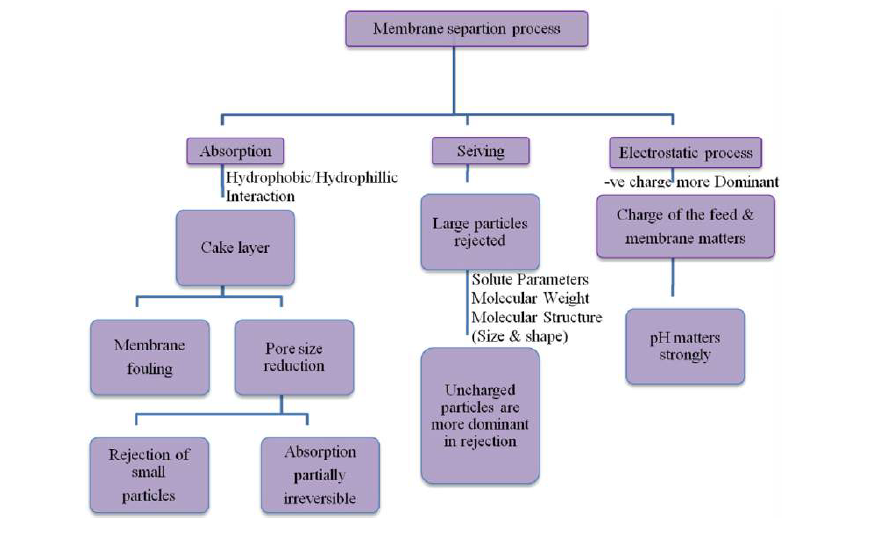
Figure 2.2: Basic principles used in membrane separation (adopted from Padaki et al. 2015)
Of the four membrane filtration technologies, microfiltration has the largest pore size (0.1 to 3 mm) thus it is popularly used for the removal of solids suspended in produced water as well as reduction of turbidity (Igunnu and Chen, 2012). This technology can be used is either dead-end filtration of cross-flow. On the other hand, ultrafiltration pore sizes are between 0.01 and 0.1 mm and they are used in removing color, odor, colloidal organic matter and viruses from the produced water (Colorado School of Mines, 2009). Ultrafiltration method is considered to be the most effective option for the removal of oil from produced water as compared to the other traditional separation methods. In addition, ultrafiltration is more efficient in the removal of hydrocarbons, suspended solids, and dissolved components from produced water as compared with microfiltration (He & Jiang, 2008). Both microfiltration and ultrafiltration work in low transmembrane pressure of about one to 30 psi and can be used as a pre-treatment method for desalination but it can’t remove salt from water. For microfiltration and ultrafiltration, ceramic membranes and polymeric membranes are used in water treatment. This method doesn’t require chemicals except in the periodic cleaning of the membranes and pre-coagulation where chemicals are used to enhance the removal of contaminants (Igunnu and Chen, 2012).
Both reverse osmosis and nanofiltration are pressure driven membrane technologies. The osmotic pressure of the feed solution is suppressed by the application of hydraulic pressure which forces clean water to diffuse through the dense non-porous membrane (Spiegler & Kedem, 1966). Reverse osmosis with seawater is able to remove contaminants as small as 0.0001 mm, but its main disadvantage is scaling and fouling of the membrane. With the appropriate pre-treatment technology to deal with the membrane fouling and scaling effect, reverse osmosis membrane technology would be an excellent method for treating produced water. The capital costs involved in reverse osmosis depend on the location of the site, the materials of construction, and the size of the rejection required while operational costs depend on the price of energy and total dissolved solids level in the feed water. Nanofiltration membranes are used for the treatment of produced water on both pilot and bench scales, however, this technology is not effective than reverse osmosis.
2.3.2 Thermal technology
These methods are used in regions where energy cost is relatively cheap. Thermal technologies were the method of choice for desalination of produced water before membrane technology was developed (Igunnu and Chen, 2012). The major technologies under its category are; multistage flash distillation, vapor compression distillation, and multieffect distillation. To achieve a higher efficiency with thermal technologies, hybrid thermal desalination plants, for example, multieffect distillation and vapor compression distillation are used. Up to the recent years, membrane filtration technologies have been the option of choice for many in the treatment of produced water, but with recent development in thermal processes, they have become attractive and highly competitive methods for treating produced and contaminated water (Colorado School of Mines, 2009).
The multistage flash distillation process is a robust technology for desalination of brackish and sea water. Its operation is based on evaporation of water by reduction of the pressure instead of raising the temperature (Igunnu and Chen, 2012). Multieffect distillation process involves the use of sufficient energy for the conversion of saline water to steam which upon condensation is recovered as pure water. The use of multiple effects is to improve the efficiency and minimize the energy consumed. Vapor compression distillation is a water desalination technology that is well established for treating seawater and reverse osmosis concentrate (Colorado School of Mines, 2009). The vapor generated in the evaporation change is thermally or mechanically compressed raising the temperature and pressure of the vapor. The condensation heat is returned to the evaporator and used as a source of heat. Lastly, multieffect distillation – vapor compression hybrid has been used recently for the treatment of produced water. The major advantage of this method is the increased production and enhanced energy efficiency.
Even though membrane and thermal treatment technologies are the most popular methods used in the treatment of produced water, other methods include biological aerated filters which consists of permeable media using aerobic conditions, hydrocyclones which use physical methods for separation of solids from liquids on the basis of density, gas flotation which uses fine gas bubbles to separate suspended particles that are not able to separate through sedimentation, evaporation pond which is an artificial pond that requires relatively large space for effective evaporation of the water by solar energy, adsorption which is used generally as a polishing step in the treatment process, media filtration used for the removal of oil and grease from produced water, ion exchange technology, chemical oxidation, electrodialysis reversal, freeze-thaw evaporation, dewvaporation, and macroporous polymer extraction technology (Igunnu and Chen, 2012; Colorado School of Mines, 2009).
2.3.3 Gas Flotation System
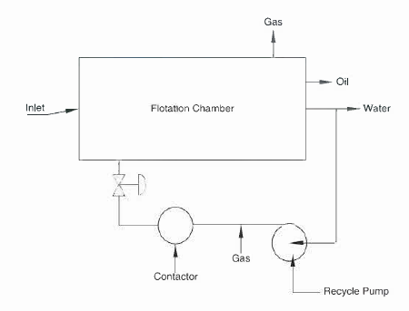
Figure 2.3: Conventional Gas Flotation system (Adopted from Saththasivam et al. 2016)
Gas flotation method is an effective option for the removal of oil-grease from produced water. Through the method, it is possible to achieve higher separation efficiency primarily through increasing adhesion and collision efficiencies. Collision probability is increased through a reduction in gas bubble size and increment of amount of gas used for flotation (Saththasivam et al. 2016). The small size of the bubble also helps in increasing adhesion efficiency. Oil droplets are normally smaller than gas bubbles and this helps in the process as oil spreads on the surface of the bubble more easily when the gas bubble are smaller. As argued by Walsh (2012), it is not economical to generate a lot of small bubbles, therefore, apart from manipulating the concentration and size of the gas bubbles, the efficiency of gas flotation can be enhanced through coalescing oil droplets. This can be done through the addition of coagulants which promote coalesce of the oil droplets making them collide and adhere better with the gas bubbles. Fluid path during the process I another factor used to improve the oil-water separation process. Mild turbulence and swirl motion promote gas-oil collision and adherence, in addition, swirl motion promotes adhesion by driving gas and oil to the core of the flotation chamber. This method, however, requires that post flotation treatment methods be used for the purpose of removing dissolved hydrocarbons from the produced water.
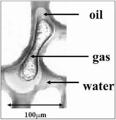
Figure 2.4: Spreading oil droplet on gas bubble (Adopted from Saththasivam et al. 2016)
The treatment target quality of the produced water is primarily determined by the regulatory framework based on the disposal strategy option selected. As a result, there are various produced water standards across regions.
2.3.4 Gravity settling
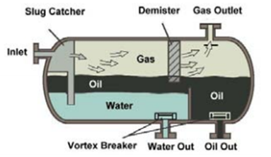
Figure 2.5: Gravity Separator (Adopted from Devold, 2013)
While technologies that are gravity based are widely used in various oil and gas firm for the separation of water from oil and grease, gas flotation systems are more preferred due to a number of advantages; higher loading rate and shorter retention time, smaller and compact footprint, a more efficient separation especially in the removal of smaller and lighter particles, and a better quality of the effluent in the presence of chemicals. In addition, it is not possible to remove the free and dispersed heavy oil through the gravitational settling technologies because of the minor differences in density between the heavy oil and the continuous fluid. Through gas flotation systems, it is possible to highly enhance density difference, which is the primary force that drives gravitational separation (Saththasivam et al. 2016; Kharoua, Khezzar & Saadawi 20l3). In gas flotation, gas bubbles are able to attach on the heavy oil and thus reduce significantly the net density of oil aggregates providing the buoyancy required for flotation to occur.
2.4 Produced water standards
The regulation of produced water in most countries and regions is done through three criteria; oil and grease concentration, produced sand/solids, and toxicity. However, the details of these regulations do vary greatly across countries and regions.
2.4.1 United States regulatory structure
In the US, regulations are by the BOEMRE (Bureau of Ocean Energy Management, Regulations, and Enforcement) and they are for four primary regions. These regions are Region 4 (Eastern Gulf of Mexico), Region 6 (Western Gulf of Mexico), Region 9 (Offshore California), and Region 10 (Arctic Waters of Alaska) (Fluor Enterprises, Inc. 2009). As per the Clean Water Act of 2009, all discharges of pollutants are prohibited unless they are authorized by the National Pollutant Discharge Elimination System (NPDES) permits. In addition, the Act requires that NPDES permits limit pollutants first on the basis of economically achievable treatment technologies and then include additional limits for protection of the quality of water.
New point sources of produced water have different NPDES regulations from the existing point sources. For new source discharges, they must adhere to the standards that have been set as per the performance of technology that has been proven to bear the greatest degree of reducing effluent. The new source performance standards (NSPS) are required to be a representation of the most stringent numerical values realizable.
The quality of produced water is governed by the US offshore regulations on oil and grease concentration, prohibition of offshore discharges of produced sand, and toxicity limitation. Produced water discharges are limited to 29 mg/l and 42 mg/l on a monthly average and a daily maximum basis respectively (Fluor Enterprises, Inc. 2009).
2.4.2 Global regional agreement
For the different regulation of produced water standards around the world, some regions have formal agreements between countries in a given areas and these have served to reduce pollution through wastewater.
2.4.2.1 Baltic Sea Convention and HELCOM standards
The Helsinki commission or HELCOM works towards the prevention of marine environment of the Baltic Sea from pollution and it is an intergovernmental corporation between Estonia, Denmark, Finland, the European community, Latvia, Germany, Poland, Lithuania, Russia, and Sweden (Fluor Enterprises, Inc. 2009). The current convention entered into force in January 2000 and HELCOM is the governing body for the “Convention on the Protection of the Marine Environment of the Baltic Sea Area”. The convention requires that the best environmental practices and the best available technologies be used for the prevention of pollution of the Baltic Sea.
2.4.2.2 Barcelona Convention Protocols (Mediterranean Countries)
The Mediterranean Action Plan (MAP) is the first ever regional seas program under United Nations Environmental Program (UNEP) and through it, 16 countries in the Mediterranean region adopted the Convention for the Protection of the Mediterranean Sea against Pollution (Barcelona Convention). Currently, the contracting countries are 22 and are Albania, Algeria, Bosnia and Herzegovina, Croatia, Cyprus, European Union, Egypt, France, Greece, Israel, Italy, Lebanon, Libya, Malta, Monaco, Montenegro, morocco, Slovenia, Spain, Syria, Tunisia, and turkey. The objective of the Convention is to assess and control marine pollution, to integrate the environment in social and economic development, to ensure sustainable management of natural marine and coastal resources, to protect the marine environment and coastal zones through prevention and reduction of pollution, and lastly, to eliminate pollution on sea or land as far as possible (Fluor Enterprises, Inc. 2009).
2.4.2.3 Kuwait Convention and Protocols (Red Sea Region)
Adopted in 1978 and enforced in 1979, the Kuwait Regional Convention for Co-operation on the Protection of the Marine Environment from Pollution objective is to prevent, abate, and combat pollution of the marine environment in the region. Contracting countries are Iran, Bahrain, Iraq, Kuwait, Oman, Saudi Arabia, Qatar, and the United Arab Emirates (Fluor Enterprises, Inc. 2009). To combat pollution through oil and other harmful substances in emergency cases, the Marine Emergency Mutual Aid Centre (MEMAC) was established with the convention framework. The convention creates high priority for combating oil and hydrocarbon pollution and this is reflected in the protocol on land-based sources for ballast, bilges, slopes, and other operations that produce water discharges. The convention also affects brine mud and water from oil and gas drilling and extraction operations from onshore operations, toxic sludge and oil from crude oil and other refines products from storage facilities, emissions and effluents from petroleum refineries, fertilizer and petroleum firms, and emissions from natural gas flaring and desulfurization firms (Veil, 2006).
2.4.2.4 OSPARCOM (North Sea Countries)
The treaties of Oslo and Paris commission (OSPARCOM) were signed in 1992 for the regulation and protection of the marine environment in the northeast Atlantic region. An internal committee referred to as the OSPARCOM is responsible for the working of these treaties. Fifteen countries are party to these treaties and they include Belgium, Denmark, Finland, France, Germany, Iceland, Ireland, Luxembourg, the Netherlands, Norway, Portugal, Spain, Sweden, Switzerland, and the United Kingdom. As a result of the treaties, oil discharges through produced water have reduced by an average of 20% in the areas under the treaties. The objectives of OSPAR concerning harmful products are to stop discharges, emission, and losses of harmful products by 2020. The ultimate goal of the treaties it to achieve a near background level of harmful products in the marine environment similar to those of the natural occurring substances and close to zero of the man-made substances (Fluor Enterprises, Inc. 2009).
Table 2.1: Produced Water Standards (adopted from Veil, 2006).
| Country | Produced water offshore standards (Oil in water) | Source/ legal basis | |
| Libya | 40 mg/L, 100 mg/L max | Barcelona Convention | |
| Qatar, Kuwait, Oman & Saudi Arabia (Middle East) | 40 mg/L avg.,100 mg/L max | KUWAIT Convention | |
| Norway | 30 mg/L (R*-2006/4) | OSPAR Convention | |
| United Kingdom | 30 mg/L (R*-2006/4) | OSPAR Convention | |
| France(North Sea) | 30 mg/L (R*-2006/4) | OSPAR Convention | |
| Germany (North Sea) | 30 mg/L (R*-2006/4) | OSPAR Convention | |
| Spain(North Sea) | 30 mg/L (R*-2006/4) | OSPAR Convention | |
United States |
29 mg/L and 42 mg/L max | 40 CFR 435-NPDES |
2.5 Libyan Oil and Gas Sector
As of January 2011, Libya had a total of 46.4 billion barrels of total proven reserves and the country produced about 1.65 million barrels of crude oil per day in 2010. This production was about 150,000 bpd short of capacity but still above the production quota set by the Organization of Petroleum Exporting Countries (OPEC) (Openoil, n.d). Analysts have estimated that the country has the potential to produce up to 3 million bpd of oil. About two-thirds of the Libyan oil production is from the Sirte Basin, about 25 percent of the production is from the Murzuq basin, and the majority of the remaining fraction from the offshore Pelagian Shelf Basin that is located near Tripoli. As of February 2010, Libya had plans to increase her oil reserve estimates with incentives for increased exploration but infrastructural constraints and contract renegotiations, and uncertainties as a result of Open quotas slowed recent increases in foreign investment.
Libya’s oil industry is state-owned by the National Oil Corporation (NOC) and it has the responsibility of implementing the Exploration and Production Sharing Agreements (EPSA) with international oil companies. International oil companies working in Libya are working in exploration, production, transportation, and refining and they include Eni, Repsol, Statoil, Shell, BP, Total SA, Occidental, OMV, ConocoPhillips, Hess, and ExxonMobil (Openoil, n.d).
2.5.1 Mellitah Oil and Gas company B.V. (MOG)
Mellitah Oil and Gas Company considered as the biggest oil and gas company in Libya. It is an exploration and production (E & P) company. The main head office is in Tripoli. Its main business is production of hydrocarbons from its offshore and onshore fields and pumping them through hundreds of kilometres of pipelines to the Libyan coast (MOG, 2016).
MOG is a joint venture between Libyan National Oil Corporation (N.O.C) and the Italian ENI company. They are equal share with 50% each. MOG was established in 2008 by Resolution No. 253 in agreement with the N.O.C and Eni North Africa. As of 2006, MOG was producing 323,000 barrels of oil equivalent (BOE) per day which constituted record production rate. The products produced by the company include natural gas, crude oil, and condensates (Openoil n.d). In addition, MOG is an important producer of natural gas in the country. It is exported to Italy through subsea pipeline by Greenstream Company.
MOG operates five major onshore and offshore oil and gas fields i.e., Bu Attifel , El Feel, Wafa, Bouri, Bahr Essalam. The company also operates an oil and gas terminal and a treatment plant at the Mellitah complex (MOG, 2016).
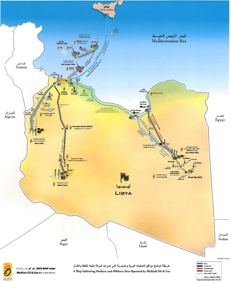
Figure 2.6: Offshore and onshore oil and gas fields at MOG (Adopted from MOG, 2016)
3 Research methodology
3.1 Two cases study as method
A case study methodology is adopted for two oil fields. The study is in two oil companies, Mellitah Oil and Gas (MOG) Company and Royal Dutch Shell. The study focuses on how produced water is treated and disposed of in each of the companies.
3.2 Mellitah Oil and Gas Company ; Bu Attifel Oil Field
In 1967, onshore Bu Attifel field was discovered. It is one of the deepest oil reservoirs in the country around “15,000 feet”. The oil production has commenced since the early 1970s and it is operated by owners Italian ENI North Africa Company and Libyan National Oil Corporation (NOC). The Bu Attifel Oil Field is one of the largest reservoirs which have advanced in the separation of water which would otherwise be the main contaminant to the oil produced. Bu Attifel field has 39 wellheads and associated flow lines which are connected through a gathering system to a center where oil & and gas and water separation and stabilization is done. The system is designed to such that it achieves the required crude oil characteristics and specifications necessary for separating the gas and water contained in the well fluids. The process of separation consists of three stages where at the end, each of the three constituents from the well is channeled to different storage units (Bu Attifel Field, 2010).
During the first stage, the gas and liquid content from the wellheads are whereby the gas is routed to two directions after measurements of the pressure level; one goes to the Meter Bank while the other is conveyed to the high-performance flares. The liquid is discharged into the second stage for under the right pressure and temperature. During the second stage, gas, oil, and water are separated in and horizontal vessel. The gas is fed to medium gas comprehension or in some instance to the flare while the two liquids which form an interface by the virtue of the different densities are discharged separately through control valves. The water is sent to a flash tank for degassing and then to API Separator before discharging it into dessert/evaporation ponds. The liquid oil continues to the final stage of the process.
The third stage which is also the final stage is designed for advanced gas, oil and water separation. The gas received flows to the medium comprehension stage while the oil and water are separated just like in the previous stage. Oil is then sent to the storage tanks while the water is measured, taken to the degassing chambers before finally disposing it into the evaporation ponds. During the three stages, pressure and temperature are regulated precisely since they determine a lot the refined level of the three constituents from the wellheads. The amount received at each stage is measured to keep a consistency of the percentage achieved for each of the stages (Bu Attifel Field, 2010).
The highest percentage of water is received from the 2nd and 3rd separation stages with the little amount being received from the discontinuous streams in the storage tanks, and flash tank. The maximum water expectation based on the design capacity is 65, 000 BPD in Bu Attifel Oil Field.
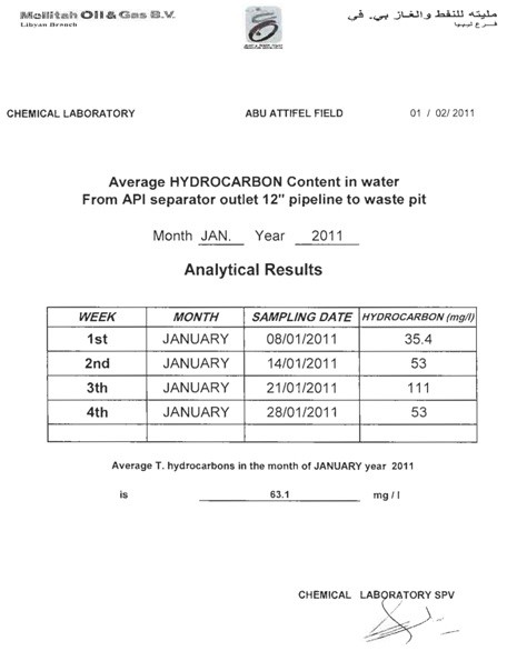
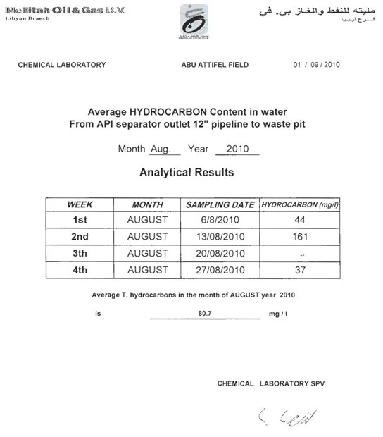
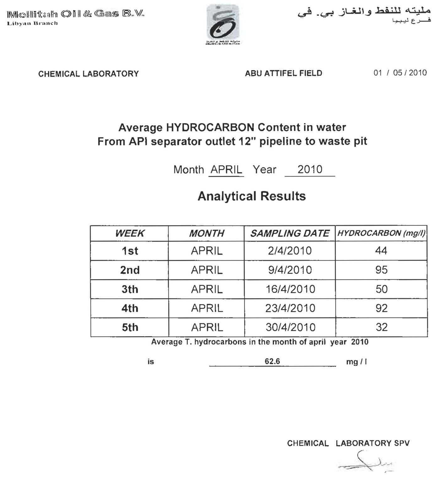
Bu Attifel field has used API separator technology to oily water separation. The API separator divided in two sections; it allows the separation of oil from oily water by difference of gravity. Oily water separation is improved by heating the mixture with a steam-coil. Separated oil is recovered using pumps PD3 and PD4 that recycle the oil to gas boots. Treated water overflows to a connected water pit and send by pumps P9 A/B for disposal to evaporation ponds. As stated in appendix A number of hydrocarbons in the water sample at the end of the process varies greatly with samples taken from the Bu Attifel oil field data sheet showing as low as 32 mg/l and as high as 161 mg/l. This technology is less effective than Corrugated Plate Interceptor (CPI) technology due to old manufacturing technology.
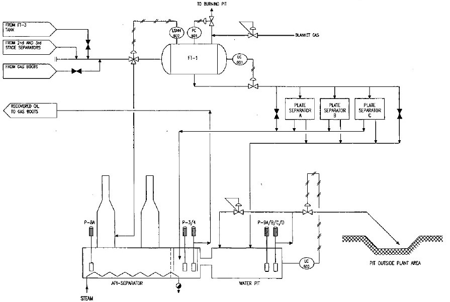
Figure 3.1: API Separator sketch at Bu Attifel field (Adopted from Bu Attifel Field, 2010)
Table 3.1: API Separator Design Specification at Bu Attifel oil field (Adopted from Bu Attifel Field, 2010)
| Item | API Separator | Water Pit |
| Service | Oil/Water Separation
(By gravity) |
Water Collection |
| Type | slotted pipe skimmer | – |
| Dimensions (LxWxH) | 34′ 5″x 32′ 10″x 4′ 3″ | 32′ 10″x 9′ 10″x 4′ 3″ |
| Pressure | Atmosphere
(1 ATM = 1.013 Bar) |
Atmosphere |
| Temperature | 220 oF = 104.4 oC | 220 oF = 104.4 oC |
| Capacity/Volume | 692 BBL | 163.5 BBL |
| Oil content, inlet | 2000 PPM (1 PPM= 1 mg/L) | 50 PPM |
| Oil content, outlet | 50 PPM | 50 PPM |
| Material | Concrete | Concrete |
Water separated from Bu Attifel Oil Field is considered a useless waste which is discarded off in evaporation ponds. MOG has no measures or alternatives that can the water become a useful by-product from the wellheads. It is also worth noting that the heating system that is required to maintain the content at the right pressure and temperature incorporated water which is sourced a fresh. The technology used determines a lot about the water quality that MOG produces and it is debatable whether the quality of water received at the end of the process is the best that possible. There were wide discrepancies between the volumes in a given month, which apart from being attributed to the source, can also be as a result of the approach used (Bu Attifel Field, 2010).
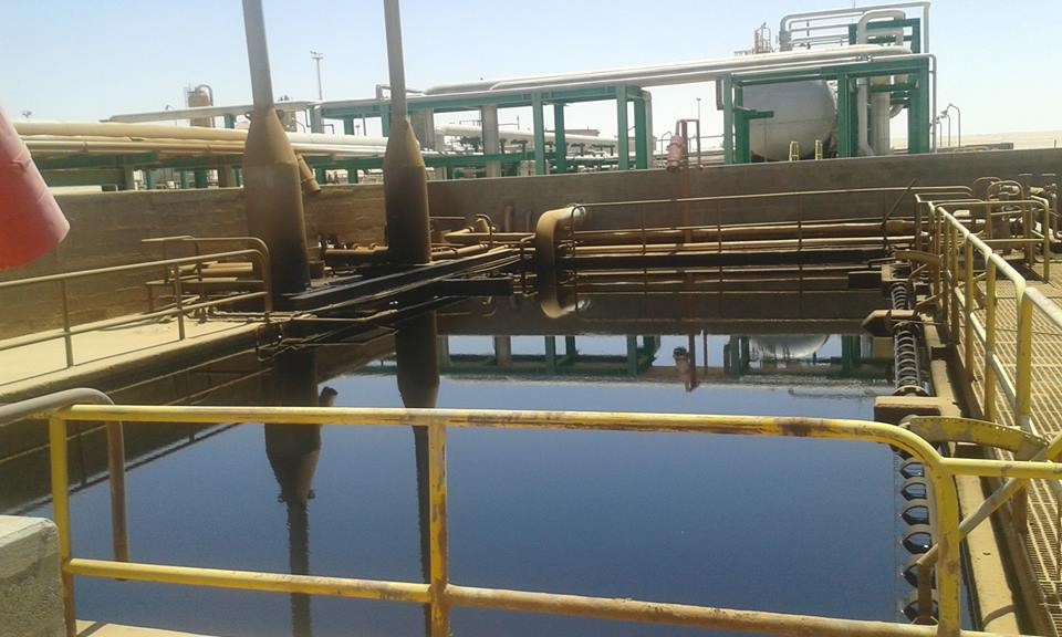 Figure 3.2: API Separator photo at Bu Attifel oil field (Adopted from MOG, 2016)
3.3 Royal Dutch Shell
The Royal Dutch Shell commonly referred to as Shell is an Anglo-Dutch oil and gas multinational companies with headquarters in both London and Hague. It was as a result of the merger between Shell- Mex and BP in 1976 when the companies, having been operated separately joined forces amid tuff economic conditions. In the United Kingdom, the company still uses the original flag bearer and is among the leading oil and gas production companies. The main wellheads are situated in the North Sea where drilling and extraction are done and transported to on-shore for separation and further refinery (The Shell United Kingdom, 2016; Archives hub, n.d). In Shell fields, oil-water separation is achieved through Corrugated Plate Interceptor (CPI) which among other advantages has the highest efficiency and very cost-effective.
CPI was developed by using Shell’s technology which was originally developed by Hazen and Camp based on specific gravity to separate the oily wastewater in treatment plants. Currently, a few changes have been developed whereby the plastic packing are placed in parallel to enhance the gravity separation. It consists of corrugated plates that are angled at 45 degrees to the horizontal to allow for the separation to occur which are placed in a basin like a vessel. The basin is then equipped with adjustable effluents and oil weirs. The CPIs chambers are built underground with series of units that the produced water moves before it being cleaned as wastewater for discharging (Chiyoda Corporation, 2016).
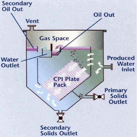
Figure 3.3: Corrugated plate interceptor, CPI (Adopted from Arthur et al, 2005)
The mode of operation is quite simple since unlike conventional methods, there is no need to break the oil droplet unnecessarily; the oil is fed to the system by gravity. In cases where there might be solid waste. The influent flows into a quiescent zone located in the ahead of the CPI packing. For effective separation, the liquid should be slowed down to have a laminar flow by the time it reaches the CPI. The liquid with the lighter specific gravity (density) rises to peaks of the corrugation and continues to rise till it reaches the troughs located at the inlets. At this instance, it flows unimpeded by the primary flow into the bucket. The heavier liquid will then flow out through the lower sections of the pack into the effluent trough (Zuniga, 2014).
Further treatments are given to the effluent to remove dissolved gasses from a floatation chamber at atmospheric pressure. The wastewater is placed in above 6’ containers for a retention period of between 10 and 40 minutes to tap out any gas dissolved due to the induced pressure.
Oil exploration and production are controlled by one of the most elaborate structures in the country. The Oil & Gas, UK, is chartered with the responsibility of drafting the rules and regulation which must be followed by the respective companies. The body also acts as a watchdog to ensure that the rules are followed to the letter and even provides relevant information concerning the geological and seismic surveys, productions, offshore & onshore water storage and transfer and any other relevant information (Oil & Gas UK, n.d.).
4 Results
From the above cases, it was observed that a lot of wastewater after the oil-water separation is discarded. In the scenario for Bu Attifel, the by-product is channeled into evaporation ponds which can be considered to be some form of waste. There are international guidelines on conservation as stated by the United Nations and Environmental Program which is complimented by additional national policies on water management (UNEP, 1997). If these regulations are met during the treatment process, this water can find use in various ways either in the oil company or related plants. This research has outlined some ways in which this by-product can be used in a more economical way rather than having to discard it out in the desert. These solutions are discarded below.
4.1 Solution 1: To sell the produced water as a by-product of the oil field
During oil extraction, water can constitute to more than 33% of the product that is brought to the surface (Bu Attifel Field, 2010). In some instances especially in offshore drilling, this amount can be even above 50% which should be separated from the oil before any further refinery process can take place. Water tables are known to lie at shallow depths compared to the oil rigs hence in many cases, the drill bits must pass through this zone before they can reach it. On financial grounds, it presents an additional cost to the exploration and production process since it has no economic value to the company. Water has been identified as a major factor that is considered in exploration as it is a key determinant of the whole process.
It is also interesting to note that oil well centre consume a large amount of water. Water is integral to all industrial process and a fundamental necessity for the survival of the labour force in the work environment. To maintain the extracted oil at the right temperature in the piping system, hot water I pumped through concentric pipes. It also injected into the wells to heat the oil to the less viscous status which will then be pumped to the surface. The overall plant maintenance also requires water for cleaning operations. In many wells, they drill separate wells specifically for water that will be used for these and other purposes including human consumption (Arthur, Langhus and Patel 2005).
From an analytical point of view, it can be seen that this is an extra overhead cost which has absolutely no returns. Apart from the initial drilling process of a water supply well, there are additional costs associated such as maintenance of the submersible pumps. The study proposed that the wastewater which is dumped in evaporation ponds can be used for the above purposes rather than having to incur an extra cost in finding a water source. It has the advantage of being readily available and the fact that it is a by-product of the extraction process would be considerably low. There are specifications which have been set forth by governing bodies such as ISO rules and regulations which set forth the standards to be adhered to in a safe working environment. It is the strong belief of this study that the cost of purifying the waste water to attain such recommendation is far less compared to the having to drill a water well.
In other cases, it is even possible to sell this wastewater to nearby oil fields for use in their operations. If such cases, the by-product would become a source of revenue to the plant. Irrespective of the use, it can be seen that the wastewater has a potential of reducing the operational cost of the plant if it covers the water aspect of the whole process or can even be a source of income to the plant. Being able to sell oil, gas, and water can be a great investment to the plant.
4.2 Solution 2: Utilizing the water after treatment in the re-injection in reservoir
Extraction of oil from long depths is not an easy task. On normal scenarios, only about a third of the total reservoir can be brought up to the surface hence the need to come up with the option to be able to exploit the maximum possible. The extraction process creates a void which should be filled so that the recovery process can be continued. Since the drill hole is central, there are sections within the reservoir which are far from reach presenting a problem of how to reach it. In normal cases, water is pumped to fill the void, create the necessary pressure and push the oil toward the wellhead to boost further recovery from that particular reservoir. The water is sought from outside sources, taken through the necessary treatment before it can be pumped as required (Zuniga, 2014).
This presents another cost to the plant as the water, river water or in other cases, separate water well is drilled to cater for the demand. Wastewater can function quite well for this purpose since in the first place it requires minimum treatment so that it can meet the standards required. If see water is used as an alternative, it undergoes a purifying process to remove any compound that can be corrosive or course scaling on the pipe used. The process of creating evaporation pond is just an unnecessary cost on discarding the water there can affect the seasonal water points. To counteract this pollution, the company must alternative between the seasons to ensure that there is the minimum interaction of the waste water and the rain water. Even with such careful disposal, it is a must to treat the wastewater to meet certain regulations set by the environment.
The surest and safest of discarding the by-product is through re-injection. In any surface discarding, the wastewater can sip into the ground and with time mix with other water bodies posing a threat to living things. It will also help maintain the serenity of the area as no unnecessary evaporation ponds will be dug to create a reservation. After the possible oil has been recovered, the water will have been returned from the very source where it was obtained in the first place.
4.3 Solution 3: Use the latest technology to obtain less contaminated water for safe disposal to the environment.
Governmental and nongovernmental organizations, as well as the corporate world, are becoming increasing conscious about the environment with the case from all corners about the need to conserve the environment. One of the ISO charters, ISO 14000, is purely about environmental management (ISO, 2016). Countries like the United Kingdom have set forth the national standards which oil exploring companies to adhere to before, during and after the recovery of oil in the environment. Companies which fail to observe such rules and regulations face strict penalties and in some cases, their activities banned in the country. Petroleum and petroleum by-products pose one of the greatest threats in the event of water and land pollution. The reclamation process is quite difficult and such pollution can declare a given species extinct within a short duration even before the process has kicked off.
Ensuring that the water from the oil heads can be safely released to the environment has been the greatest challenge to oil exploring companies. This is the main reason why Bu Attifel Oil Field under MOG sought the later option of having to dig the evaporation ponds in the desert to dispose of it. However, water is becoming a rare commodity around the globe and Libya having a large percentage of the land mass being a desert, it can be treated to a level that makes it salable or usable for irrigation purposes. The process has been difficult in the past but with the current technology, it is possible to have it purified to level whereby it can be used for general household chores and farming.
In the modern world, every resource should be used for the maximum benefit that it can offer to the human population and discard wastewater should be a thing of the past. Meeting the standards can be quite achievable compared to the recent as technology has explored more avenues for reaching the said standards.
4.4 Solution 4: Other Alternatives
It is possible to avoid the production of the wastewater to the surface. Polymer gels can be used to block the water contributing fissures during the drills process hence reducing the amount of water that mixes with the oil in the first place. Downhole Water Separators can also be used to separate the water from oil/gas streams and re-inject it into the suitable formation (Zuniga, 2014). This option, however, elegant it might sound is not quite possible and might come along with certain challenges depending on specific factors of the wellhead.
5 References
(Introduction):
Ahmadun F, Pendashteh A, Abdullah LC, Biak DRA, Madaeni SS & Abidin ZZ, (2009), Review of technologies for oil and gas produced water treatment, Journal of hazardous materials 170, 530-551.
Arthur JD, Langhus BG & Patel C. (2005), TECHNICAL SUMMARY OF OIL & GAS PRODUCED WATER TREATMENT TECHNOLOGIES, ALL CONSULTING, LLC.
Devold H, (2009), Oil and gas production handbook: An introduction to oil and gas production, ABB oil and Gas.
Igunnu ET and Chen GZ, (2012), Produced water treatment technologies, Int. J. Low-Carbon Tech. doi:10.1093/ijlct/cts049.
Sutherland K. (2012). Oil and gas: Separation processes in oil and gas extraction, Filtration Separation. Retrieved from http://www.filtsep.com/view/24224/oil-and-gas-separation-processes-in-oil-and-gas-extraction/
Veil JA, Puder MG, Elcock D and Redweik R Jr. J. (2004), A White Paper Describing Produced Water from Production of Crude Oil, Natural Gas, and Coal Bed Methane, US DOE W-31-109-Eng-38.
…………………………………………………………………………….
(Literature review):
Argonne National Laboratory, Veil JA, Puder MG, Elcock D & Redweik Jr. RJ, (2004). A White Paper Describing Produced Water from Production of Crude Oil, Natural Gas, and Coal Bed Methane, U.S. Department of Energy National Energy Technology Laboratory Under Contract W-31-109-Eng-38,
Colorado School of Mines. (2009). Technical Assessment of produced water treatment technologies. An Integrated Framework for Treatment and Management of Produced Water. RPSEA Project 07122-12, Colorado, 8–128.
Devold H, (2013), Oil and gas production handbook An introduction to oil and gas production, transport, refining and petrochemical industry, ABB Oil and Gas, Oslo.
Fluor Enterprises, Inc. (2009). Ultra deep water discharge of produced water and/or solids at the seabed. Research Partnership to Secure Energy for America. Retrieved from www.rpsea.org/media/files/project/96ca04c4/09121-3100-01-FR-UDW_Discharge_Produced_Water_Solids_Seabed-04-24-12_P.pdf on July 25, 2016
He Y & Jiang ZW, (2008). Technology review: treating oilfield wastewater. Filtr Sep 45:14–6.
Igunnu ET and Chen GZ, (2012), Produced water treatment technologies, International Journal of Low-Carbon Technologies Advance, 0, 1–21
Kharoua N, Khezzar L & Saadawi H, (20l3). CFD Modelling of a Horizontal Three-Phase Separator: A Population Balance Approach, AmericanJournal of Fluid Dynamics, 3(4): 101-118. DOl: 10.5923/j.ajfd.20l30304.03
Openoil, (n.d). Libya Oil Almanac: An OpenOil Reference Guide. Retrieved from http://openoil.net/wp/wp-content/uploads/2012/08/Libya-PDF-v-2.0.pdf on July 19, 2016
Padaki M, Surya Murali R, Abdullah MS, Misdan N, Moslehyani A, Kassim MA, Hilal N & Ismail AF, (2015). Membrane technology enhancement in oil–water separation. A review, Desalination 357, 197–207.
Saththasivam J, Loganathan K & Sarp S, (2016). An overview of oil-water separation using gas flotation systems, Chemosphere 144, 671-680
Spiegler KS & Kedem O, (1966). Thermodynamics of hyperfiltration (reverse osmosis): criteria for efficient membranes. Desalination 1:311–26.
Veil JA, (October 19, 2006). Why Are Produced Water Discharge Standards Different throughout the World? Argonne National Laboratory. Retrieved from http://ipec.utulsa.edu/Conf2006/Papers/Veil_prodwater.pdf on July 19, 2016
Walsh J, (2012). Selection and Troubleshooting of Flotation Equipment for Produced Water Handling. SPE Web Event. Retrieved from http://petrowatertech.com/wp-content/uploads/2015/08/Flotation-Webinar29Nov2012-21.pdf on July 25, 2016
Xu P & Drewes JE, (2006). Viability of nanofiltration and ultra-low pressure reverse osmosis membranes for multi-beneficial use of methane produced water. Sep Purif Technol 52:67–76
…………………………………………….
(Research Methodology and Results):
Archives hub, (n.d.). GB 1566 SMBP: Shell-Mex and BP Archive, BP Archive. Retrieved from http://archiveshub.ac.uk/data/gb1566-smbp on August 16, 2016.
Arthur D, Langhus BC, and Patel C, (2005). Technical Summary of Oil and Gas Produced Water Treatment Technologies, ALL Consulting, LLC.
Bu Attifel Field (2010). Operating Processes, Melitah Oil and Gas B.V, Libya Branch.
Bu Attifel Field (2010). Produced Water Systems, Melitah Oil and Gas B.V, Libya Branch.
Bu Attifel Field (2010). Water Samples from API separator – S560, Melitah Oil and Gas B.V, Libya Branch.
Chiyoda Corporation (2016). CPI Oil Separator. Retrieved from https://www.chiyoda-corp.com/technology/en/environment/cpioilseparator.html on August 15, 2016.
Oil and Gas Uk, (n.d.). Retrieved from http://oilandgasukenvironmentallegislation.co.uk/contents/pages/table_list.htm on August 15, 2016.
Shell United Kingdom (2016). ENERGY FROM DEEP WATER. Retrieved from http://www.shell.co.uk/energy-and-innovation/energy-from-deep-water.html#iframe-L3dlYmFwcHMvZGVlcF93YXRlci92Mi9pbmRleC5odG1s on August 15, 2016.
UNEP, (1997). Environmental management in Oil and Gas Exploration and Production, UNEP Technical Publications.
Zuniga, (2014). Separation Technologies in Oil and Gas Production, Norges teknisk-naturvitenskapelige universitet.
………………………………………….
6 Appendixes
6.1 Appendix A: Three water samples illustrate oil content (mg/L) in water disposal from API Separator outlet at Bu Attifel Oil Field (MOG)
INSTANT PRICE
Get an Instant Price. No Signup Required
We respect your privacy and confidentiality!
Share the excitement and
get a 15% discount
Introduce your friends to The Uni Tutor and get rewarded when they order!