")


")
Produced Water literature review
-
Chapter Two-Literature review
- Oil Production process
The oil and gas production process is broadly defined in terms of its use in the oil and gas production stream. These include exploration, upstream, midstream, refining, and petrochemical (Devold 2013). Upstream is typically the phase of production and stabilization of oil and gas and midstream is the oil and gas treatment phase.
While in the past exploration involved inspection of surface features among them tar seeps or gas pockmarks, today exploration is done using a series of surveys that start with a broad geographical mapping. Geographical mapping is done through increasingly advanced methods for example; passive seismic, magnetic and gravity surveys that give data to advanced analytic tools that identify the potential for rocks rich with hydrocarbon.
Oil production is either offshore or onshore for the two require specific and specialized technology as a result of the oil and gas being extracted. In addition, the natural state of the resource, unconventional or conventional is also a factor to consider in the production process of oil and gas. Nevertheless, the general oil production process starts in the upstream phase at the wellhead. Once drilling is completed and a well verified to be commercially viable of natural gas or oil extraction, it has to be “completed” to allow for the resource to flow out. This process involves strengthening the oil well hole with casing, evaluation of the temperature and pressure of the formation, and installation of the proper equipment to allow for efficient flow of the resource (Argonne National Laboratory et al. 2004). The process of completion is differentiated into dry completion and subsea completion which are onshore and below the surface respectively.
For onshore oil production to be economically viable, it has to be from a few dozen barrels a day and more. The oil gathering network can be very large with production from thousands of wells which are a hundred kilometers apart and feed to a plant through a gathering network. However, the oil extraction process will depend on the nature of the well, with the easier method being for free-flowing wells. For the small reservoir, extracted oil is collected in a holding tank from where it is picked on regular intervals by railcars or trucks for processing at a refinery (Devold 2013). For onshore wells that are located in oil-rich areas, production can be up to thousands of barrels per day and this is sent from the plant to a refinery through a pipeline or tankers. Ordinarily, oil into a refinery can be from various license owners and this makes metering of individual well-streams necessary.
Unconventional oil production targets crude oil that is very heavy and from tar sands which become economically extractable with new technology and such oil attracts higher prices. To be extracted, heavy crude oil may need to be heated and diluted. Tar sand are strip-mined or extracted with steam for they have lost their volatile compounds (Devold 2013). With drilling technology and fracturing of the reservoir which began in 2007, it is possible to produce shale gas and liquids in higher volumes. As a result, the US, in particular, has been able to reduce her dependence on hydrocarbon important. Other countries that are increasingly producing unconventional crude oil are Canada, china, Russia, Australia, Mexico, and Argentina. The hydrocarbons found in unconventional reserves may be more two to three times than those found in conventional reservoirs.
In offshore oil production, a range of different structures is used and these depend on the size and water depth. In the recent years, there has been an increase in the pure sea bottom installations that are connected to multiphase piping to the shore and with entirely no offshore topside structures (Devold 2013). These new developments have replaced the outlying wellhead towers and deviation drilling is being used to reach the different parts of the reservoir from few locations of the wellhead clusters. Some of the common structures used in offshore oil production process are shallow water complex, gravity base, compliant towers, floating production which includes Floating Production Storage and Offloading (FPSO), Tension Leg Platform (TLP), semi-submersible platforms, and SPAR, and subsea production systems.
Swallow water complex, which are several independent platforms that have different parts of the process and utilities are linked with gangway bridges. Each of the platforms has wellhead riser, accommodation, processing, and power generation platforms. Gravity base is made up of huge concrete fixed structures that are placed on the bottom, normally with oil storage cells in a “skirt” that is on the bottom of the sea. All parts of the process and utilities are received by the large deck in large modules. Compliant towers which are more like fixed platforms are made up of a narrow tower that is attached to a foundation on the seafloor and extends up to the platform (Devold 2013). The tower is flexible therefore it can operate in a much deeper water level for it can absorb much of the pressure exerted by the sea and the wind. Subsea production systems involve wells that are located on the floor of the sea with petroleum extracted at the seabed and “tied-back” to an offshore facility of a pre-existing production platform. The well is drilled using a movable rig and the oil extracted is transported through an undersea pipeline and to a processing facility using a riser.
Floating production, on the other hand, has all the topside production systems located on a floating structure with subsea or dry wells. The first is the EPSO which is a standalone structure which doesn’t need external structures like storage or pipelines. Crude oil is offloaded to a shuttle tanker on a regular basis and depending on the storage capability. The second is the TLP which is made up of vertical tendons that are connected to the sea floor by pile-secured templates and they hold the structure in place. The third floater type is semi-submersible platforms which have a similar design to TLP but without a taut mooring which allows for more vertical and lateral motion. Semi-submersible platforms are used generally with flexible risers and subsea wells. The last floating production type is the SPAR which is made up of a single tall floating cylindrical hull which supports a fixed deck (SPAR is not an acronym and it gets its name from its resemblance to a ship’s spar). The cylinder is tethered to the bottom by a series of cables and lines and it does not extend all the way to the seabed (Devold 2013).
In onshore production, the individual well streams are brought into the main production center through a network of pipelines and manifold systems. The purpose of these gathering pipelines is to allow for the creation of “well sets” to allow for the selection of the well with the best reservoir utilization flow composition (Devold 2013). In offshore, the dry composition wells that are located in the main field feed directly into the production manifolds while the subsea installations and outlying wellhead towers feed through multiphase pipelines that flow back into the production risers. Risers are a system of pipes that rise to the top of the production structure (Devold 2013). The next phase in the production process is separation.
The resource from a given well will vary greatly. While some wells have for instance pure gas that can be taken directly for treatment, others will have a combination of gas, oil, and water with other various contaminates that must be processed and separated. Separation facilities are in various forms and design with the classic variant being the gravity separator (Devold 2013). In this process, the oil well resource flow is directed into a horizontal vessel with a retention period of about five minutes to allow for gas to bubble out, the water fraction to settle at the bottom and for oil to be taken out t the middle level. The pressure level is often reduced in several stages so as to allow for controlled separation of the components depending on their volatility.
With oil removed from the mixture, it is subjected to another treatment process to rid it of any contaminants that could include mineral components as well as further processing to achieve the various final commercial products. From this process, water is simply a byproduct of the process and in the modern day oil and gas industry, this has become a useful resource for various uses among them, reinjection into the well. However, before it is used for whatever option the firm deems suitable, it has to be treated to the required standard as per the given use.
Before oil is loaded on a vessel, which marks the final stage of the upstream phase, it is stored. In offshore production facilities, those without a direct pipeline connection will normally rely on crude storage in the hull or base, and then a shuttle tanker offloads it periodically. For the larger production complexes, they generally have an associated tank farm terminal which allows for storage of the different grades of crude oil hence accommodating for demand changes, transport delays, and other unexpected inconveniences in the supply chain. The role of metering stations is to allow operators to manage and monitor the natural oil exported from a production facility. To effectively and successfully implement this duty, these stations use specialized meters to measure oil as it flows through the pipeline and thus not impeding its movement. Such metering measures the volume transferred to a consumer or other divisions within the company and it is referred to as transfer metering (Devold 2013). The importance of this type of metering is that it forms the basis for invoicing the transferred product and allow for calculation of taxes and revenue sharing among the partners.
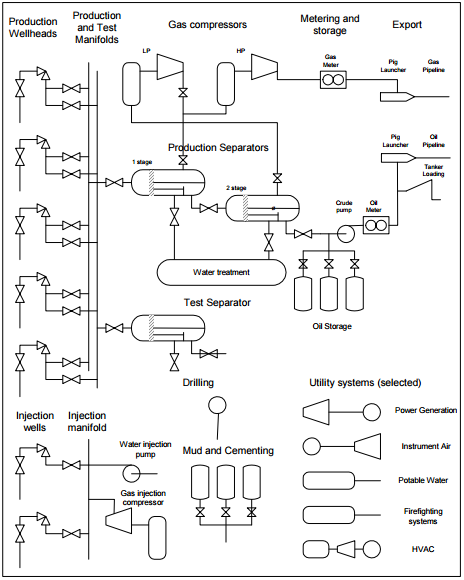
Figure 1. Oil production overview (adopted from Devold 2013)
In the tail end processes in the production of oil is refining, which is done for the purpose of providing a defined range of products based on agreed specification. The simple refineries have a distillation column for the separation of crude into fractions with the relative quantities of each fraction being directly dependent on the crude used (Devold 2013). To produce the required quantity and quality of end products, it is necessary to obtain a variety of crudes which can be blended to a suitable feedstock. Moreover, this strategy has become really essential for it is one of the methods that can guarantee the economic viability of a modern refinery through the use of various methods among them cracking, reforming, additives, and blending. Crude blending has the potential to produce products that can meet the demands of the market both in quality and quantity at premium prices. The role of a refinery is not limited to refining but also includes operating products distribution terminals which dispense their products to bulk customers, for example, gasoline stations, airports, industries, and ports.
- Produced Water as a byproduct
Naturally occurring rocks in a subsurface formation are generally permeated with fluids among them oil, gas, and water or some combinations of these fluids. As argued by Saththasivam, Loganathan and Sarp (2016), the rock with the most oil-bearing formations is entirely saturated with water before the oil and gas extraction process begins. The formation of hydrocarbon reservoirs is through the less dense hydrocarbons migrating to the trap locations and displacing some of the water from the formation. As a result, reservoir rocks will normally contain both water and petroleum hydrocarbons, i.e. liquid and gas. The source of the water could include both above and below the hydrocarbon zone, from within the hydrocarbon zone, or flow from fluids injected and additives during the extraction and production process. As this stage, this water is referred to as “formation water” or “connate water” and its names changes to produced water after the reservoir is produced and the fluids extracted to the surface.
Produced water, therefore, is any water present in a reservoir occurring with the hydrocarbon resource and it is produced to the surface as a mixture with the natural gas or the crude oil. On production, hydrocarbons are a mixture of fluids and solids and it’s typically composed of gaseous or liquid hydrocarbons, dissolved or suspended solids, produced water, produced solids which include sand and/or silt, and injected additives and fluids that are placed into the formation with the aim of enhancing the exploration and production processes (Argonne National Laboratory et al. 2004).
In the process of oil and gas extraction, produced water is produced as a byproduct. It is certainly not the product of interest in the drilling process. Owing to the fact that water is a naturally occurring substance in any geographical environment, it is impossible to avoid water in the extract during oil and gas extraction and production regardless of how sophisticated the equipment is. As a result, it becomes essential that the water component in the oil and gas extract is separated at the initial stages of oil and gas process resulting to produced water. Various methods are used for the separation of water with the oil and gas and the process to be used will primarily be determined by the nature of the crude oil extract. The technological options available include gravity settling (skim vessels, API tanks, and parallel and corrugated plate separation), hydrocyclone, chemical treatment, coalescing media, gas flotation, media filtration, and membrane separation.
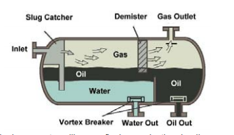
Figure 2. Gravity Separator (Adopted from Devold 2013)
While technologies that are gravity based are widely used in various oil and gas firm for the separation of water from oil and grease, gas flotation systems are more preferred due to a number of advantages; higher loading rate and shorter retention time, smaller and compact footprint, a more efficient separation especially in the removal of smaller and lighter particles, and a better quality of the effluent in the presence of chemicals. In addition, it is not possible to remove the free and dispersed heavy oil through the gravitational settling technologies because of the minor differences in density between the heavy oil and the continuous fluid. Through gas flotation systems, it is possible to highly enhance density difference, which is the primary force that drives gravitational separation (Saththasivam et al. 2016; Kharoua, Khezzar & Saadawi 20l3). In gas flotation, gas bubbles are able to attach on the heavy oil and thus reduce significantly the net density of oil aggregates providing the buoyancy required for flotation to occur.
Despite being a byproduct in the oil and gas production process, produced water has become a major factor in the oil and gas industry with respect to environmental pollution and the volume of produced water globally. Produced water is made up of various elements and thus, it is not a single commodity. The properties of produced water, both chemical and physical vary greatly depending on the geographical location of the oil field, the geological formation which the produced water has been in contact with hitherto, and the type of hydrocarbon being produced (Kharoua et al. 20l3). Research has shown that the properties of produced water, as well as the volume produced in a given well, can vary throughout the lifetime of the well. Additionally, if waterflooding operations are implemented, then the properties and volumes of produced water could vary even more dramatically as injected water is introduced into the reservoir’s formation.
Given the increased interest in produced water, knowledge of the components of the specifically produced water is important for compliance with regulations in choosing the appropriate management option. Various produced water disposal strategies are available and the most appropriate are chosen by a given oil and gas company based on mainly economic benefits. Some of the most common produced water disposal strategies include reinjection into the well. In both offshore and onshore oil and gas production, oil and grease receive the most attention as constituents of produced water with salt content, expressed in terms of salinity, Total Dissolved Solids (TDS), or conductivity, being the primary constituent of concern in onshore oil and gas production operations. In addition to these, other elements in produced water are both organic and inorganic compounds and these vary greatly depending on geographical location and time of the well (Saththasivam et al. 2016).
Given the nature of produced water, it is generally impossible to remove the various components through the basic and popular gravitational separation technology thus additional treatment technologies are required. There are various produced water treatment methods and the choice of any is dependent on a number of factors among them; the nature and constituents of the produced water, oil and gas firm capabilities, the disposal method available for the produced water, and economic benefits.
- Treatment technologies
The approaches available for the treatment of produced water are many. The appropriate option will largely depend on the geographical location of the oilfield, the regulatory framework applicable, technical feasibility by the given oil and gas firms, cost, and the presence of the right equipment and infrastructure. The most common options that are being used currently for the management of produced water include; underground reinjection, beneficial reuse, and discharge into the environment (Saththasivam et al. 2016; Argonne National Laboratory et al. 2004). In the past, the methods used were basically chosen based on convenience and those that are least expensive. Given this shift, and the realization by oil and gas production firms that produced water can either be of value or a cost to the overall operations, new produced water treatment methods are available and largely used in the industry today.
- Membrane filtration technology
This technology uses membranes which are microporous films with pore ratings, and they selectively separate a fluid by filtering out the various components. There are four established membrane separation methods; ultrafiltration, microfiltration, reverse osmosis, and nanofiltration (Xu & Drewes 2006). The four technologies all work through different mechanisms to separate the fluid with the constituents. Reverse osmosis separates ionic and dissolved components, microfiltration separates particles suspended in the produced water, ultrafiltration separates macromolecules, and nanofiltration is a selective method separating multivalent ions. While microfiltration and ultrafiltration technologies can be used as standalone strategies for the treatment of produced water, reverse osmosis, and nanofiltration technologies have to be employed in the desalination of produced water (Padaki et al. 2015). Nanofiltration and reverse osmosis are therefore the best-suited treatment technologies when seeking to reduce the salt content of produced water, which is common for offshore production where produced water is mixed with the sea water.
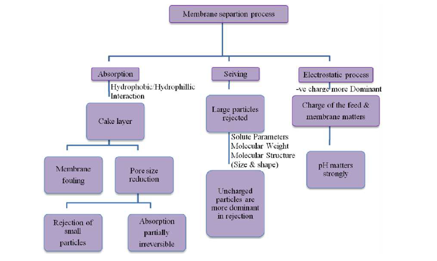 Figure 3. Basic principles used in membrane separation (adopted from Padaki et al. 2015)
Of the four membrane filtration technologies, microfiltration has the largest pore size (0.1 to 3 mm) thus it is popularly used for the removal of solids suspended in produced water as well as reduction of turbidity (Igunnu and Chen 2012). This technology can be used is either dead-end filtration of cross-flow. On the other hand, ultrafiltration pore sizes are between 0.01 and 0.1 mm and they are used in removing color, odor, colloidal organic matter and viruses from the produced water (Colorado School of Mines 2009). Ultrafiltration method is considered to be the most effective option for the removal of oil from produced water as compared to the other traditional separation methods. In addition, ultrafiltration is more efficient in the removal of hydrocarbons, suspended solids, and dissolved components from produced water as compared with microfiltration (He & Jiang 2008). Both microfiltration and ultrafiltration work in low transmembrane pressure of about one to 30 psi and can be used as a pre-treatment method for desalination but it can’t remove salt from water. For microfiltration and ultrafiltration, ceramic membranes and polymeric membranes are used in water treatment. This method doesn’t require chemicals except in the periodic cleaning of the membranes and pre-coagulation where chemicals are used to enhance the removal of contaminants (Igunnu and Chen 2012).
Both reverse osmosis and nanofiltration are pressure driven membrane technologies. The osmotic pressure of the feed solution is suppressed by the application of hydraulic pressure which forces clean water to diffuse through the dense non-porous membrane (Spiegler & Kedem 1966). Reverse osmosis with seawater is able to remove contaminants as small as 0.0001mm, but its main disadvantage is scaling and fouling of the membrane. With the appropriate pre-treatment technology to deal with the membrane fouling and scaling effect, reverse osmosis membrane technology would be an excellent method for treating produced water. The capital costs involved in reverse osmosis depend on the location of the site, the materials of construction, and the size of the rejection required while operational costs depend on the price of energy and total dissolved solids level in the feed water. Nanofiltration membranes are used for the treatment of produced water on both pilot and bench scales, however, this technology is not effective than reverse osmosis.
- Thermal technologies
These methods are used in regions where energy cost is relatively cheap. Thermal technologies were the method of choice for desalination of produced water before membrane technology was developed (Igunnu and Chen 2012). The major technologies under its category are; multistage flash distillation, vapor compression distillation, and multieffect distillation. To achieve a higher efficiency with thermal technologies, hybrid thermal desalination plants, for example, multieffect distillation and vapor compression distillation are used. Up to the recent years, membrane filtration technologies have been the option of choice for many in the treatment of produced water, but with recent development in thermal processes, they have become attractive and highly competitive methods for treating produced and contaminated water (Colorado School of Mines 2009).
The multistage flash distillation process is a robust technology for desalination of brackish and sea water. Its operation is based on evaporation of water by reduction of the pressure instead of raising the temperature (Igunnu and Chen 2012). Multieffect distillation process involves the use of sufficient energy for the conversion of saline water to steam which upon condensation is recovered as pure water. The use of multiple effects is to improve the efficiency and minimize the energy consumed. Vapor compression distillation is a water desalination technology that is well established for treating seawater and reverse osmosis concentrate (Colorado School of Mines 2009). The vapor generated in the evaporation change is thermally or mechanically compressed raising the temperature and pressure of the vapor. The condensation heat is returned to the evaporator and used as a source of heat. Lastly, multieffect distillation – vapor compression hybrid has been used recently for the treatment of produced water. The major advantage of this method is the increased production and enhanced energy efficiency.
Even though membrane and thermal treatment technologies are the most popular methods used in the treatment of produced water, other methods include biological aerated filters which consists of permeable media using aerobic conditions, hydrocyclones which use physical methods for separation of solids from liquids on the basis of density, gas flotation which uses fine gas bubbles to separate suspended particles that are not able to separate through sedimentation, evaporation pond which is an artificial pond that requires relatively large space for effective evaporation of the water by solar energy, adsorption which is used generally as a polishing step in the treatment process, media filtration used for the removal of oil and grease from produced water, ion exchange technology, chemical oxidation, electrodialysis reversal, freeze-thaw evaporation, dewvaporation, and macroporous polymer extraction technology (Igunnu and Chen 2012; Colorado School of Mines 2009).
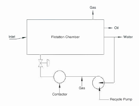
Figure 4. Conventional Gas Flotation system (Adopted from Saththasivam et al. 2016)
Gas flotation method is an effective option for the removal of oil-grease from produced water. Through the method, it is possible to achieve higher separation efficiency primarily through increasing adhesion and collision efficiencies. Collision probability is increased through a reduction in gas bubble size and increment of amount of gas used for flotation (Saththasivam et al. 2016). The small size of the bubble also helps in increasing adhesion efficiency. Oil droplets are normally smaller than gas bubbles and this helps in the process as oil spreads on the surface of the bubble more easily when the gas bubble are smaller. As argued by Walsh (2012), it is not economical to generate a lot of small bubbles, therefore, apart from manipulating the concentration and size of the gas bubbles, the efficiency of gas flotation can be enhanced through coalescing oil droplets. This can be done through the addition of coagulants which promote coalesce of the oil droplets making them collide and adhere better with the gas bubbles. Fluid path during the process I another factor used to improve the oil-water separation process. Mild turbulence and swirl motion promote gas-oil collision and adherence, in addition, swirl motion promotes adhesion by driving gas and oil to the core of the flotation chamber. This method, however, requires that post flotation treatment methods be used for the purpose of removing dissolved hydrocarbons from the produced water.
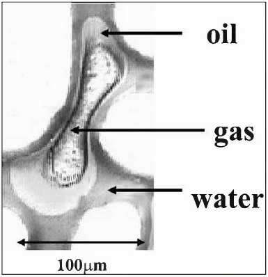
Figure 5. Spreading oil droplet on gas bubble (Adopted from Saththasivam et al. 2016)
The treatment target quality of the produced water is primarily determined by the regulatory framework based on the disposal strategy option selected. As a result, there are various produced water standards across regions
- Produced water standards
The regulation of produced water in most countries and regions is done through three criteria; oil and grease concentration, produced sand/solids, and toxicity. However, the details of these regulations do vary greatly across countries and regions.
- United States Regulatory structure
In the US, regulations are by the BOEMRE (Bureau of Ocean Energy Management, Regulations, and Enforcement) and they are for four primary regions. These regions are Region 4 (Eastern Gulf of Mexico), Region 6 (Western Gulf of Mexico), Region 9 (Offshore California), and Region 10 (Arctic Waters of Alaska) (Fluor Enterprises, Inc. 2009). As per the Clean Water Act of 2009, all discharges of pollutants are prohibited unless they are authorized by the National Pollutant Discharge Elimination System (NPDES) permits. In addition, the Act requires that NPDES permits limit pollutants first on the basis of economically achievable treatment technologies and then include additional limits for protection of the quality of water.
New point sources of produced water have different NPDES regulations from the existing point sources. For new source discharges, they must adhere to the standards that have been set as per the performance of technology that has been proven to bear the greatest degree of reducing effluent. The new source performance standards (NSPS) are required to be a representation of the most stringent numerical values realizable.
The quality of produced water is governed by the US offshore regulations on oil and grease concentration, prohibition of offshore discharges of produced sand, and toxicity limitation. Produced water discharges are limited to 29 mg/l and a maximum of 42 mg/l on a monthly and daily basis respectively (Fluor Enterprises, Inc. 2009).
- Global regional agreements
For the different regulation of produced water standards around the world, some regions have formal agreements between countries in a given areas and these have served to reduce pollution through wastewater.
-
Baltic Sea Convention and HELCOM standards
The Helsinki commission or HELCOM works towards the prevention of marine environment of the Baltic Sea from pollution and it is an intergovernmental corporation between Estonia, Denmark, Finland, the European community, Latvia, Germany, Poland, Lithuania, Russia, and Sweden (Fluor Enterprises, Inc. 2009). The current convention entered into force in January 2000 and HELCOM is the governing body for the “Convention on the Protection of the Marine Environment of the Baltic Sea Area”. The convention requires that the best environmental practices and the best available technologies be used for the prevention of pollution of the Baltic Sea.
-
Barcelona Convention and Protocols (Mediterranean Counties)
The Mediterranean Action Plan (MAP) is the first ever regional seas program under United Nations Environmental Program (UNEP) and through it, 16 countries in the Mediterranean region adopted the Convention for the Protection of the Mediterranean Sea against Pollution (Barcelona Convention). Currently, the contracting countries are 22 and are Albania, Algeria, Bosnia and Herzegovina, Croatia, Cyprus, European Union, Egypt, France, Greece, Israel, Italy, Lebanon, Libya, Malta, Monaco, Montenegro, morocco, Slovenia, Spain, Syria, Tunisia, and turkey. The objective of the Convention is to assess and control marine pollution, to integrate the environment in social and economic development, to ensure sustainable management of natural marine and coastal resources, to protect the marine environment and coastal zones through prevention and reduction of pollution, and lastly, to eliminate pollution on sea or land as far as possible (Fluor Enterprises, Inc. 2009).
-
Kuwait Convention and Protocols (Red Sea Region)
Adopted in 1978 and enforced in 1979, the Kuwait Regional Convention for Co-operation on the Protection of the Marine Environment from Pollution objective is to prevent, abate, and combat pollution of the marine environment in the region. Contracting countries are Iran, Bahrain, Iraq, Kuwait, Oman, Saudi Arabia, Qatar, and the United Arab Emirates (Fluor Enterprises, Inc. 2009). To combat pollution through oil and other harmful substances in emergency cases, the Marine Emergency Mutual Aid Centre (MEMAC) was established with the convention framework. The convention creates high priority for combating oil and hydrocarbon pollution and this is reflected in the protocol on land-based sources for ballast, bilges, slopes, and other operations that produce water discharges. The convention also affects brine mud and water from oil and gas drilling and extraction operations from onshore operations, toxic sludge and oil from crude oil and other refines products from storage facilities, emissions and effluents from petroleum refineries, fertilizer and petroleum firms, and emissions from natural gas flaring and desulfurization firms (Veil 2006).
-
OSPARCOM (North Sea Countries)
The treaties of Oslo and Paris (OSPAR) were signed in 1992 for the regulation and protection of the marine environment in the northeast Atlantic region. An internal committee referred to as the OSPARCOM is responsible for the working of these treaties. Fifteen countries are party to these treaties and they include Belgium, Denmark, Finland, France, Germany, Iceland, Ireland, Luxembourg, the Netherlands, Norway, Portugal, Spain, Sweden, Switzerland, and the United Kingdom. As a result of the treaties, oil discharges through produced water have reduced by an average of 20% in the areas under the treaties. The objectives of OSPAR concerning harmful products are to stop discharges, emission, and losses of harmful products by 2020. The ultimate goal of the treaties it to achieve a near background level of harmful products in the marine environment similar to those of the natural occurring substances and close to zero of the man-made substances (Fluor Enterprises, Inc. 2009).
| Country | Produced water offshore standards | Source/ legal basis |
| Libya | 40 mg/L, 100 mg/L max | Barcelona Convention |
| Qatar, Kuwait, Oman & Saudi Arabia (Middle East) | 40 mg/L avg.,100 mg/L max | KUWAIT Convention |
| Norway | 40 mg/L; 30 mg/L (2006) | OSPAR Convention |
| United Kingdom | 40 mg/L; 30 mg/L (2006) | OSPAR Convention |
| France(North Sea) | 40 mg/L; 30 mg/L (2006) | OSPAR Convention |
| Germany (North Sea) | 40 mg/L; 30 mg/L (2006) | OSPAR Convention |
| Spain(North Sea) | 40 mg/L; 30 mg/L (2006) | OSPAR Convention |
| United States | 29 mg/L and 42 mg/L max | 40 CFR 435 |
Table 1. Produced Water Standards (adopted from Veil 2006)
- Measuring oil standard
In the oil industry, produced water standard and in particular, the concentration of oil and grease is defined through the method through which it is measured. The methods used across the world does vary from one region to another therefore, it is very difficult to compare the various produced water standards. Produced water measurement methods can be categorized into two; direct and indirect. Direct methods do measure the mass per unit volume of oil in the produced water directly for example, the US EPA Method 1664 is based on a direct measurement method and oil and grease is defined as a mixture of those components in produced water which can be extracted in hexane at pH2 or lower and they remain after hexane has been vaporized. The amount of oil that remains in a 1 liter of produced water is weighed and the concentration of oil-to-water is reported directly in mg/l (Fluor Enterprises, Inc. 2009).
This method has the advantage that it is straightforward and it doesn’t require a standard for comparison. However, it is limited to what components can be extracted as any dispersible hydrocarbons that are non-extracted are not considered to be oil through this measurement method. This method requires trained technicians to carry it out in an accredited laboratory. As a result of being not usable in the field, operators opt to use indirect methods that use equipment and tools that are calibrated with the oil produced in the plant. This option provides the operators with a workable estimate of what the 1664 method concentration would be so that discharges can be optimized to compliance levels.
On the other hand, indirect or instrumental methods are applied to the measurement of other features of a sample of produced water which are then used to relate to a standard for determination of the mass of the oil. Before 2007, OSPAR required an indirect method using infrared (IR) analysis. In the method, tetrachloroethylene is used for the extraction of the oil from the sample of produced water after which IR absorption equipment using spectrophotometry are used to quantify the amount of oil by targeting carbon-hydrogen bonds which at a wavelength of 3.41 absorb IR energy (Fluor Enterprises, Inc. 2009). Because indirect methods don’t measure the oil components actual weight in produced water, calibration of the instrument has to be done to create a relationship between the features being measured, for example, IR absorption, and the oil concentration.
The measurements of IR absorption are plotted against known concentrations of a standard sample and the relationship must be linear otherwise, a lower standard concentration has to be used. There are a number of issues to be considered with the calibrations with the first being the composition of the standard, which has to be the same as that of the sample being analyzed. However, this is rarely the case as standards will usually be only crude oil whereas the oil in produced water includes crude oil, dissolved oil from the formation water and chemicals from treatment processes that when measured appear as oil (Fluor Enterprises, Inc. 2009).
After 2007, an alternative indirect method for measuring oil and grease concentration is produced water has been adopted and used by the OSPAR. The method uses capillary gas chromatography with a non-polar column and a flame ionization detector (FID) to analyze produced water. The gas chromatographer works through the production of a graph then the total peak area between the n-heptanes and the n-tetracontane is determined. The peak areas for aromatic hydrocarbons toluene, three isomers of xylene and ethyl benzene are subtracted from the total peak area, and the dispersed oil content is then calculated after the concentration of the dispersed oil is quantified against an external standard that consists of a mixture of two specified mineral oils.
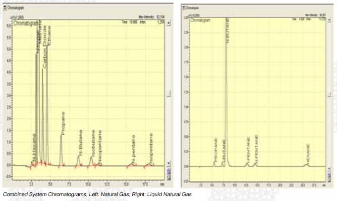 Figure 6. Gas chromatogram (adopted from Shimadzu n.d)
Based on the above, it is evident that it is difficult to compare the final mg/l concentration of a direct method analysis with the result of an indirect analysis for the simple fact that they don’t measure the same thing. Moreover, the definition of the term oil varies through the various procedures from the extraction phase to the treatment of produced water. As a result, produced water standard ought to be determined as per the specified regulatory requirements for a given region and the mg/l contraction of oil-to-water should not be compared with different measurement methods of other regions.
- Libyan Oil and Gas sector
As of January 2011, Libya had a total of 46.4 billion barrels of total proven reserves and the country produced about 1.65 million barrels of crude per day in 2010. This production was about 150000 bpd short of capacity but still above the production quota set by the Organization of Petroleum Exporting Countries (OPEC) (Openoil n.d). Analysts have estimated that the country has the potential to produce up to 3 million bpd of oil. About two-thirds of the Libyan oil production is from the Sirte Basin, about 25 percent pg the production is from the Murzuq basin, and the majority of the remaining fraction from the offshore Pelagian Shelf Basin that is located near Tripoli. As of February 2011, Libya had plans to increase her oil reserve estimates with incentives for increased exploration but infrastructural constraints and contract renegotiations, and uncertainties as a result of Open quotas slowed recent increases in foreign investment.
Libya’s oil industry is state-owned by the National Oil Corporation (NOC) and it has the responsibility of implementing the Exploration and Production Sharing Agreements (EPSA) with international oil companies. International oil companies working in Libya are working in exploration, production, transportation, and refining and they include Eni, Repsol, Statoil, Shell, BP, Total SA, Occidental, OMV, ConocoPhillips, Hess, and ExxonMobil (Openoil n.d).
- Mellitah Oil and Gas company (MOG)
MOG is a joint venture in which NOC and the Italian oil company, Eni, are equal share with 50% each. The Libyan branch of Mellitah Oil and Gas B.V. was established in 2008 by Resolution No. 253 of the People’s Committee in agreement with the NOC and Eni North America. As of 2006, MOG was producing 323000 barrels of oil equivalent (boe) per day which constituted record production rate. The products produced by the company include natural gas, crude oil, and condensates. The venture operates the Sabratha platform which is located offshore 110 km North West of Tripoli (Openoil n.d). It also bounces gas from one of the largest fields in Libya, Bahr Essalam. In addition, MOG is an important producer of gas for the Greenstream pipeline as well as for the local gas consumption in the country.
-
References
Argonne National Laboratory, Veil JA, Puder MG, Elcock D & Redweik Jr. RJ, (2004). A White Paper Describing Produced Water from Production of Crude Oil, Natural Gas, and Coal Bed Methane, U.S. Department of Energy National Energy Technology Laboratory Under Contract W-31-109-Eng-38,
Colorado School of Mines. (2009). Technical Assessment of produced water treatment technologies. An Integrated Framework for Treatment and Management of Produced Water. RPSEA Project 07122-12, Colorado, 8–128.
Devold H, (2013), Oil and gas production handbook An introduction to oil and gas production, transport, refining and petrochemical industry, ABB Oil and Gas, Oslo.
Fluor Enterprises, Inc. (2009). Ultra deep water discharge of produced water and/or solids at the seabed. Research Partnership to Secure Energy for America. Retrieved from 2009www.rpsea.org/media/files/project/96ca04c4/09121-3100-01-FR-UDW_Discharge_Produced_Water_Solids_Seabed-04-24-12_P.pdf on July 25, 2016
He Y & Jiang ZW, (2008). Technology review: treating oilfield wastewater. Filtr Sep 45:14–6.
Igunnu ET and Chen GZ, (2012), Produced water treatment technologies, International Journal of Low-Carbon Technologies Advance, 0, 1–21
Kharoua N, Khezzar L & Saadawi H, (20l3). CFD Modelling of a Horizontal Three-Phase Separator: A Population Balance Approach, AmericanJournal of Fluid Dynamics, 3(4): 101-118. DOl: 10.5923/j.ajfd.20l30304.03
Openoil, (n.d). Libya Oil Almanac: An OpenOil Reference Guide. Retrieved from http://openoil.net/wp/wp-content/uploads/2012/08/Libya-PDF-v-2.0.pdf on July 19, 2016
Padaki M, Surya Murali R, Abdullah MS, Misdan N, Moslehyani A, Kassim MA, Hilal N & Ismail AF, (2015). Membrane technology enhancement in oil–water separation. A review, Desalination 357, 197–207.
Saththasivam J, Loganathan K & Sarp S, (2016). An overview of oil-water separation using gas flotation systems, Chemosphere 144, 671-680
Shimadzu, (n.d). System GC Catalog: Natural Gas, Petrochemical and Other Standard Applications. Retrieved from http://www.ssi.shimadzu.com/products/literature/gc/shimadzu_system_gc_catalog.pdf on July 25, 2016
Spiegler KS & Kedem O, (1966). Thermodynamics of hyperfiltration (reverse osmosis): criteria for efficient membranes. Desalination 1:311–26.
Veil JA, (October 19, 2006). Why Are Produced Water Discharge Standards Different throughout the World? Argonne National Laboratory. Retrieved from http://ipec.utulsa.edu/Conf2006/Papers/Veil_prodwater.pdf on July 19, 2016
Walsh J, (2012). Selection and Troubleshooting of Flotation Equipment for Produced Water Handling. SPE Web Event. Retrieved from http://petrowatertech.com/wp-content/uploads/2015/08/Flotation-Webinar29Nov2012-21.pdf on July 25, 2016
Xu P & Drewes JE, (2006). Viability of nanofiltration and ultra-low pressure reverse osmosis membranes for multi-beneficial use of methane produced water. Sep Purif Technol 52:67–76.
INSTANT PRICE
Get an Instant Price. No Signup Required
We respect your privacy and confidentiality!
Share the excitement and
get a 15% discount
Introduce your friends to The Uni Tutor and get rewarded when they order!