")


")
Integrated Project: Design of main truss and columns
-
Description of Facility
The building is composed of a single main floor on top of two staircases with support serving as its main frame. The building is simplified to a rectangular shape with a gable type roof.
The building has a total floor area of 280 m2, which is meant for gallery show. No division will be constructed within the building’s walls to accommodate more people coming into the gallery or exhibit. The main floor is supported by beams on both ends where a staircase is also situated. It is 8 meters above the floor level, to provide an outside parking area at the bottom of the building while saving land space.
Objectives:
The main objective of this project is to design a gallery building that is similar to the previous term project and demonstrate understanding of the concepts learned throughout the course. Among the specific objectives of this project are:
- Determine the loads produced on the structure based on materials chosen.
- Calculate the load and design the critical members of the structure such as the slab, beam, column and truss.
-
Structural Idealization
Figure 1 shows the common load acting on a building. Snow load (S) Wind load (W) and dead load (D) are expected to act on the roofing, while dead load and live load (L) acts on the bottom part of the truss. Wind action is directed towards the roof, while there is also wind load acting internally or from the inside of the building. Dead load and live load act on the first floor of the building.
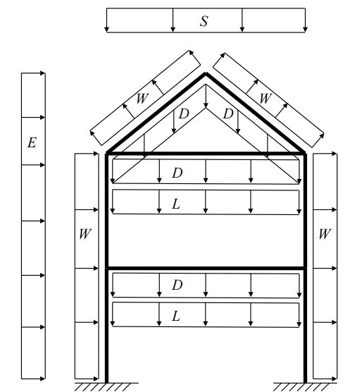
Figure 1. Load Analysis
Estimation of Loads
Loads are determined based of the structural idealization presented previously. Load analysis is performed considering the main truss and columns only assuming that other components are affected insignificantly. Among the loads considered are live load, dead load, wind load and snow load. Upon performing some calculations, the combination of each loads was determined and the design of critical members are prepared.
Roof Truss Load Analysis
Given the design specifications of the roof truss:
Total Span of the Truss = 4@1.75 m = 7 m
Truss Spacing = 10 m
Pitch Angle = 15⁰
The amount of load acting on the roof truss is determined. Among the loads considered are the wind load, dead loads due to weight of materials used and live loads.
- Wind Load Analysis
The roof is designed to be inaccessible to people except for usual maintenance operations such as painting and minor repairs (Category H). For a sloping roof, and category H (EBCS-1 EN 1995).
qk = 0.25 kN/m2
Qk = 1.0 kN
External Wind Pressure
The wind pressure acting on the external surface of the structure is computed using the formula:
We = qref x Ce(Ze) x Cpe
Where, qref = reference wind pressure
qref = ρ/2 Vref2
where, ρ = air density (from site with elevation from sea level > 2000m)
ρ = 0.94 Kg/m3
Vref = reference wind velocity
Vref = Cdir x Ctem x Calt x Vref0 = 1x1x1x22 m/s
Thus,
qref = ρ/2 Vref2
qref = 227.48 N/m2
Ce = pressure coefficient that accounts the effect of terrain roughness, topography, and height above the ground given the mean wind speed. It is computed as:
Ce(z) = Cr2(Z)Ct (Z){1+[7KT/Cr(Z)xCt(Z)]}
Where KT is the terrain factor.
For the site location with at least 20% of the surface is covered with buildings with a mean height of 15 m,
KT = 0.24
Cr(Z) is the roughness coefficient, computed as:
Cr(Ze) = KT ln (Ze/Z0) for Zmin < Z
Cr(Ze) = Cr(Zmin) for Z < Zmin
Where: Z0 is the roughness length (1 m)
Zmin is the minimum height (16 m)
Z = height of the building, roof level (17 m)
Computing for Cr(Ze),
Cr(Ze) = KT ln (Ze/Z0) for Zmin < Z
Cr(Ze) = 0.24 ln (17/1)
Cr(Ze) = 0.68
For zones, unaffected by topography, Ct(Ze) = 1.
Ce(Ze) = 0.682 x 12 x {1+[(7 x 0.24)/(0.68 x 1)]}
Ce(Ze) = 1.602
Cpe is the external pressure coefficient from the Appendix A of EDBC 1 EN 1995.
For 0 degrees, for the wind angle on the roof, the value for Cpe is equal to 0.20.
Solving for the wind pressure on the external surface:
We = qref x Ce(Ze) x Cpe = 227.48 x 1.602 x (0.20)
We = 0.073 kPa
For 90 degrees, for the wind angle on the roof, the value for Cpe is equal to -1.96.
Solving for the wind pressure on the external surface:
We = qref x Ce(Ze) x Cpe = 227.48 x 1.602 x (-1.96)
We = -0.714 kPa
Internal Wind Pressure
Wi = qref x Ce(Ze) x Cpi
For closed buildings, Cpi is equal to 0.8 and -0.5, as the extreme values. Thus, the wind load at the roof is given as:
Wi = 0.292 kPa
Wi = – 0.182 kPa
Critical Wind Load
The net negative wind pressures, (external + internal) is equal to -1.006 kPa, and the net positive wind pressure is equal to 0.255 kPa.
- Load on Purlin
The material of construction selected for the roofing is EGA – 300, as shown in the figure below.
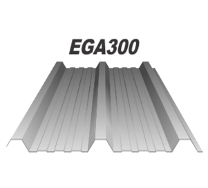
Figure 2. EGA – 300
For a thickness of 0.4 mm, the load per area brought by the roofing material (treated as dead load):
DL1 = 0.0382 kPa
For the purlins, the self-weight is equal to (DL2) 0.0286 kPa.
Consider the live load as: LL = 0.25 kPa
Wind Load acting on the purlin:
WL = 0.255 kPa x cos 15⁰
WL = 0.246 kPa
Total Load computation:
Total Load = 1.3DL + 1.6LL + WL
Total Load = 0.733 kPa
Using the data for the allowable load, and the thickness of the EGA roof cover, the purlin spacing based on table is:
Purlin spacing = 1.75 to 2.0 m
Considering the given design parameters for this project, with roof width span of 7.0 m and the pitch angle of 15⁰, the suggested purlin spacing is 1.81 m.
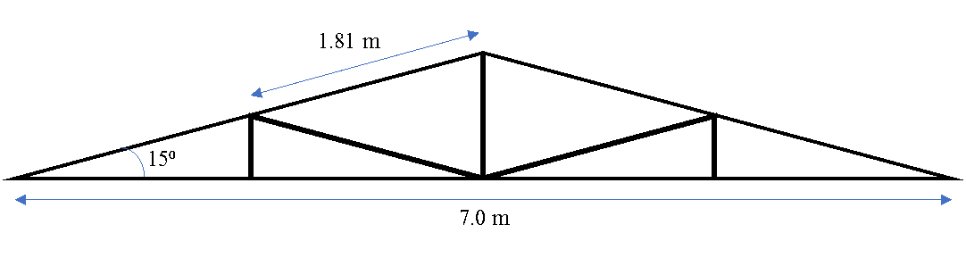 Figure 3. Roof Truss Design Layout (Drawn to Scale)
- Load on Sag rods
The maximum axial force on the sag rod is equal to 5/8 Wind Load. Choosing a sag rod with a diameter of 10 mm, the weight of the sag rod will be about 0.05 kPa, which is within the maximum limit for a maximum stress of 138 MPa.
- Roof Total Load Analysis
Dead Load
Consider the total weight of the roof = roofing + purlins + sag rods
= 0.0286 kPa + 0.0382 kPa + 0.05 kPa
= 0.1168 kPa
Purlin Spacing, Sp = 1.81 m
Truss Spacing, St = 10 m
Thus, the concentrated roof loads on truss joints is given by:
= 0.1168 kPa x Sp x St
= 2.11 kN
Assume that the weight of the truss itself is equal to 1 kN/m, Therefore the concentrated self-weight on truss joints is equal to:
= 1 x 7/4 = 1.8 kN
Dead load on top joints,
Ptop = 2.11 + 1.80 = 3.91 kN
Dead load on bottom joints,
Pbot = 1.80 kN
Total Dead load on end Joints
Pend = 2.11/2 + 1.80 = 2.86 kN
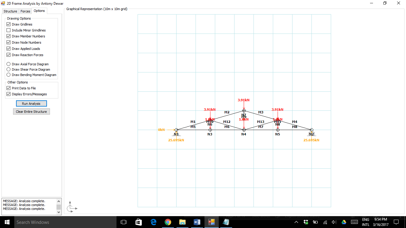
Figure 4. Dead Load Analysis
Wind Load
Based on the previous computation, positive wind acting on the purlin is equal to 0.255 kPa, while the negative wind is -1.006 kPa. Thus, the reaction in the purlin is computed as:
Positive wind, R = 0.255 kPa x Sp x St = 4.6155 kN
Rx = 1.1946 kN
Ry = 4.4582 kN
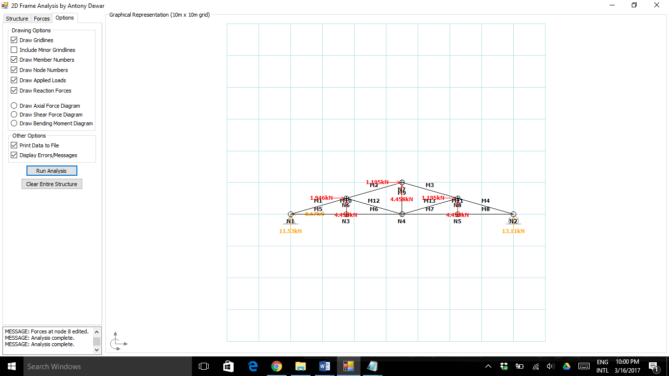
Figure 5. Wind Load Analysis
Combination Load Acting on the Roof Truss:
| Member | Dead Load, kN | Wind Load, kN | Length, m | Total Load, kN | ||||
| Axial | Shear | Axial | Shear | Axial | Shear | |||
| Top Diagonal | 1 | 12.794 | -1.8267 | -13.952 | 2.4599 | 1.82 | -1.158 | 0.6332 |
| 2 | 14.841 | 0.75905 | -18.596 | -1.1981 | 1.82 | -3.755 | -0.43905 | |
| 3 | 13.862 | -0.92053 | -18.596 | 1.1981 | 1.82 | -4.734 | 0.27757 | |
| 4 | 10.251 | 1.8301 | -13.952 | -2.4599 | 1.82 | -3.701 | -0.6298 | |
| Bottom Horizontal Cord | 5 | -7.4643 | -1.8112 | 12.739 | 2.3668 | 1.75 | 5.2747 | 0.5556 |
| 6 | -11.181 | 0.68747 | 16.491 | -1.093 | 1.75 | 5.31 | -0.40553 | |
| 7 | -11.794 | -0.84106 | 16.491 | 1.093 | 1.75 | 4.697 | 0.25194 | |
| 8 | -9.3539 | 1.7164 | 12.739 | -2.3668 | 1.75 | 3.3851 | -0.6504 | |
| Vertical Cord | 9 | -1.8122 | 0.29702 | 4.0037 | 0 | 1 | 2.1915 | 0.297021 |
| 10 | 2.4987 | 3.7167 | -1.6599 | 3.752 | 0.5 | 0.8388 | 7.4687 | |
| 11 | 2.5575 | -2.4397 | -1.6599 | 3.752 | 0.5 | 0.8976 | 1.3123 | |
| Diagonal inside | 12 | -0.86375 | 0.28404 | 1.6499 | -0.48061 | 1.82 | 0.78615 | -0.19657 |
| 13 | -0.50205 | -0.40116 | 1.6499 | 0.48061 | 1.82 | 1.14785 | 0.07945 | |
Other Structural Load Considerations
The following loads were considered for designing the slab and beams, based on the ACI 318-05.
Slab
Dead Load = 0.5 kPa
Live Load = 3.0 kPa
Walls
Dead load = 1.5 kPa
Beam Loads
Live Load = 3 kN/m2 (due to load on Floor Slab)
Dead Loads = 0.5 kN/m2 (due to tiling finish on Floor Slab)
= 24 kN/m3 x 0.25m = 6 kN/m2 (due to self – weight of Floor Slab)
= 1.5 KN/m2 (due to Block work partitions)
Total Beam Load:
Wu = 1.2 DL + 1.6 LL + Anticipated Beam Weight
= 1.2 (1.5 KN/m2 x 4m + 6.5 kN/m2 x 5m) + 1.6 (3 kN/m2 x 5m) + 6 kN/m
= 46.2 KN/m + 24 KN/m + 6 KN/m
= 76.2 KN/m
- Design of Critical Members
Truss Members
The design of truss members is carried out using the following equations.
Members under tension:
The acceptable design condition is .
Members under compression:
Slenderness ratio,
The acceptable design condition is .
Design of Bottom Cord Members:
For the bottom cord members, the maximum tensile force is 5.2747 kN and the maximum compressive force is 0.6504 kN. Since all the bottom cord members are of equal length (i.e., if effective length factor k is taken = 1, then Le = 1.75 meters), the maximum forces are taken as the design forces.
Design of Top Cord Members:
For the top cord members, the maximum tensile force 4.734 kN and the maximum compressive force is 0.6504 kN. Since all the top cord members are of equal length (i.e., if k = 1, Le = 1.82 meters), the maximum forces are taken as the design forces.
Design of Vertical and Diagonal Members:
For the vertical and diagonal members, the maximum tensile force is 2.1915 kN and the maximum compressive force is 7.4687 kN. The maximum tension acts on each member while the maximum compression acts on one member, which is 0.5 m long. Although the first two described are slightly longer (i.e., 1.82 m long), the maximum compressive forces on them are much smaller (members 11, 12, and 13). Therefore, the effective length of the design members is taken as Le = 0.5 m. The sections are designed for both tension and compression although it is likely to be governed by compression.
- Floor Slab
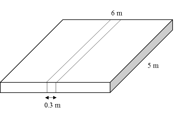
Figure 6. Slab Layout
Assumptions
Concrete f’c = 4000 psi
16mm Grade 60 main tension bars
12mm Grade 60 shrinkage bars
Concrete cover = ¾” (0.02m)
Concrete Density = 24 kN/m3
Live Load on Slab = 3 kN/m2
Dead Load on Slab = 0.5 KN/m2 (due to tiles)
Slab Thickness = L/20 = 5/20 = 0.25 m
Factored Uniform Load, Wu = 1.2 DL + 1.6 LL
= 1.2 (0.3m x 0.5 kPa + 0.3m x 0.25m x 24 kPa/m) + 1.6 (0.3m x 3 kPa)
= 2.34 kN/m + 1.44 kN/m
= 3.78 kN/m
Maximum Factored Moment, Mmax
d = slab thickness – concrete cover – 0.5 diameter of reinforcement (ACI 318-05)
d = 0.25 – 0.02 – 0.5(0.016)
d = 0.22 m
Tension Bar Spacing
Tension bar spacing requirement for moment = As per one bar / As = 0.40 m apart.
Maximum tension bar spacing between tension bars
Thus, use 16 mm tension bars at 0.3 m c/c
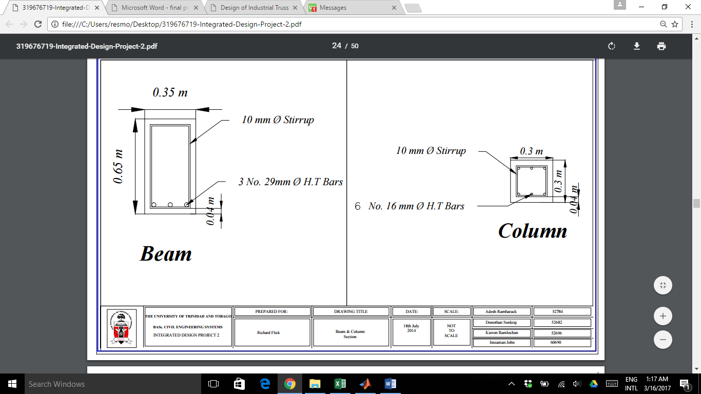
- Beam Design
Concrete f’c = 4000 PSI
3- 29mm Grade 60 main bars
10mm Grade 60 stirrups
Concrete cover = 1½” (38mm)
Concrete Density = 24 kN/m3
b = 1/2h
Minimum Suggested Thickness,
h = L/18.5 = 0.65 m
b = 0.5 x 0.65m = 0.33m or 0.35m
Mpos = 0.08wL2 = 0.08 x 76.2 kN/m x (6m)2 = 219.46 kNm
Mneg = -0.1wL2 = -0.1 x 76.2 kN/m x (6m)2 = 274.32 kNm
Based on (ACI 318-05 section 7.7.1)
d = h – concrete cover – stirrup bar diameter – ½ (main bar diameter)
= 0.65m + 0.038m + 0.01m + ½ (0.029m) = 0.588m
Based on (ACI 318-05 section 7.6.1)
ρact = As/bd = 0.00962
ρact = 0.00962 > ρmin = 0.0033, and ρact = 0.00962 < ρmax = 0.0214
Thus:
Mu = 0.9 Asfyd{1-[0.59(ρact fy /fc )]}
Mu = 387.65 kNm
Mpos = 219.46 kNm < 387.65 kNm
Mneg = 274.32 kNm < 387.65 kNm
Using the original assumption of the beam:
Beam weight = 6 kN/m (Assumed)
Actual Beam dimensions = 0.35 x 0.65 m
Beam weight = 5.46 kN/m < 6 kN/m
- Column Design
Assumptions
Concrete f’c = 4000 PSI
16mm Grade 60 main tension bars
10mm Grade 60 shrinkage bars
Concrete cover = 1.5” (0.04m)
Concrete Density = 24 kN/m3
3% Steel Reinforcement
Pu = Force from roof on column + Force from beams on column
= 342 kN + 2(1.1 x 76.2 kN/m x 6m)
= 1347.84 kN = 303006.49 lbf
Pn = Pu / ϕ = 466163.83 lbf
ϕ Pn = 0.80 x ϕ [ 0.85 f’c (Ag – Ast) + fy Ast]
0.65 x 466163.83 lbf = 0.80 x 0.65 [0.85 x 4000 (Ag– 0.03Ag) + 60000 (0.03Ag)
303006.49 lbf = 0.52 (3400Ag – 102Ag + 1800Ag)
303006.49 lbf = 2650.96 Ag
Ag = 114.3 in2
Thus, use a 12 x 12 column (144 ft2) = 0.3 m x 0.3 m column
Area of Steel Required = Ag x ρ= 0.3m x 0.3m x 0.01 = 0.0009 m2
Thus, use 6 – 16 mm diameter steel bars (0.0012 m2)
- Foundation Design
Square Pad Footing
Assumptions
Concrete f’c = 4000 PSI
25mm (#8) Grade 60 main bars
Concrete cover = 3”
qu =120 kN/m2 = 2506.25 psf
ρCONC. = 150 pcf
γs = 100 pcf
Roof Slab = 0.3m thick
Roof dead load = 25 kN/m3 X 0.3m = 7.5 kN/m2
Roof live load = 1.5 kN/m2
Total Combined Load = 1.6 LL + 1.2 DL = 1.6 x 1.5 kN/m2 + 1.2 x 7.5 kN/m2 = 11.4 kN/m2
Force on Interior Column = 11.4 kN/m2 x 6m x 5m = 342 kN
ƩFactored Loads acting on footing = Load from roof + Load from beam + Self weight of column
= 342 kN + 2(1.1 x 76.2 kN/m x 6m) + (24 kN/m x 0.3m x 0.3m x 8m)
= 1365.12 KN = 306891.19 lbf
Unfactored Loads on Footing
Roof Dead Load = 7.5 kN/m2 x 5m x 6m = 225kN
Roof Live Load = 1.5 kN/m2 x 5m x 6m = 45kN
Loads on Beam = Floor Live load = 3 KN/m2 x 5m = 15 kN/m
Floor Dead Load = 6.5 kN/m2 x 5m = 32.5 KN/m
Dead Load from Partition = 1.5 kN/m2 x 4m = 6 kN/m
Load from Self – weight of Beam = 6 kN/m
ƩLoads from beams transferred to column = 2[1.1wl]
= 2 [ 1.1 x (15 + 32.5 + 6 + 6) x 6m]
= 785.4 kN
Self – weight of Column = 24 kN/m3 x 0.3m x 0.3m x 8m = 17.28kN
ƩUnfactored Loads = 225kN + 45kN + 785.4kN + 17.28kN = 1072.68kN = 241148.06lbf
Effective Depth, d = overall depth – concrete cover – 0.5(diameter main bar)
= 20” – 3” – 0.5(1”) = 16.5”
Footing weight calculation:
= 150 pcf x 20/12 = 250 psf
Weight of soil:
= 100 pcf x 24/12 = 200 psf
Area requirements:
Appendix 1. Drawings

Truss Layout
INSTANT PRICE
Get an Instant Price. No Signup Required
We respect your privacy and confidentiality!
Share the excitement and
get a 15% discount
Introduce your friends to The Uni Tutor and get rewarded when they order!